3D Printed Tank
Summer 2021 - Present
Project Overview |
Developed Skills |
||
|
|
|
|
Objective
This project was done as a passion project to apply my current skills and learn some more about mechanical design, 3D printing, and control circuits. My goal was to create a 3D printed tank that can be remotely operated.
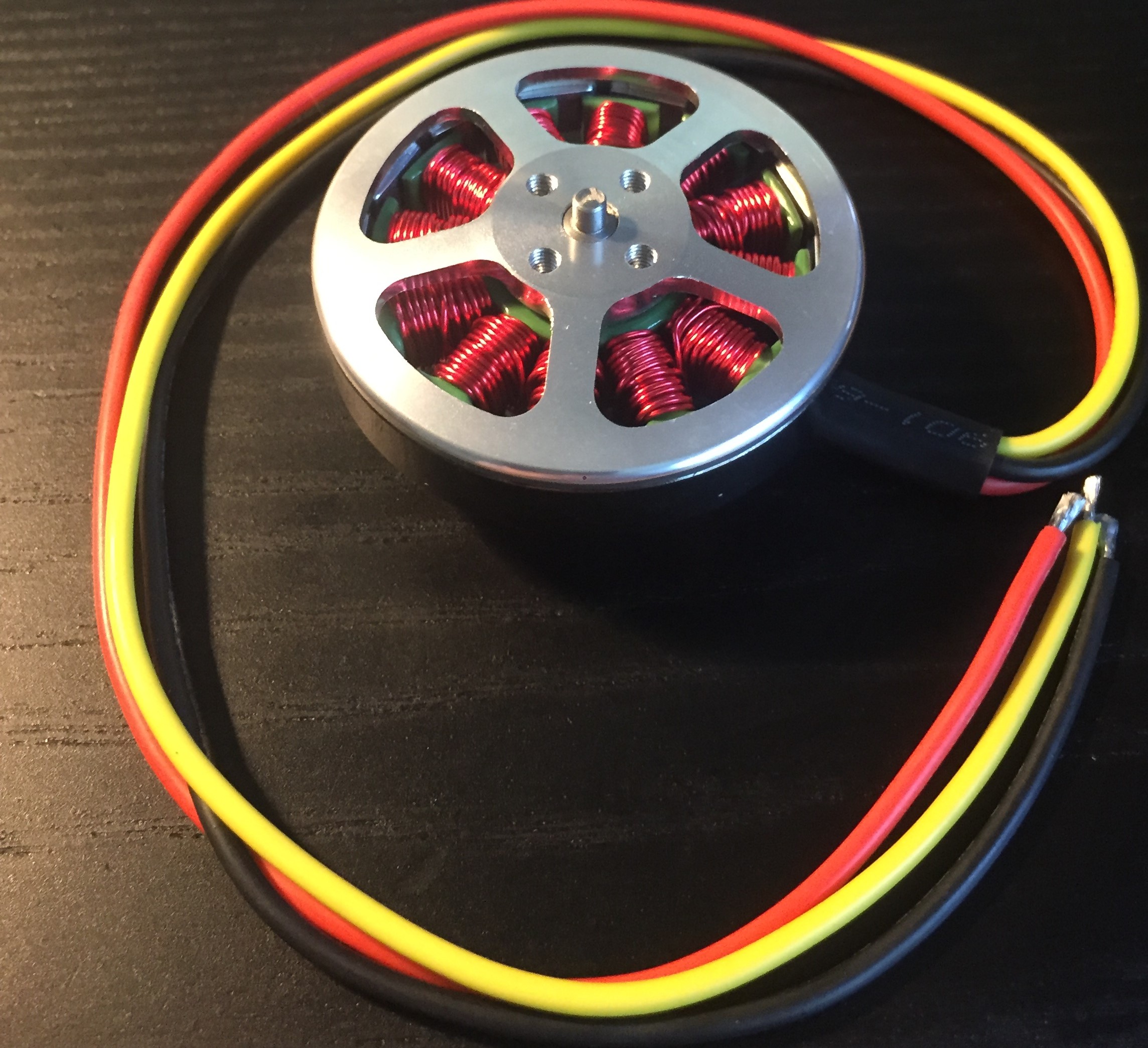
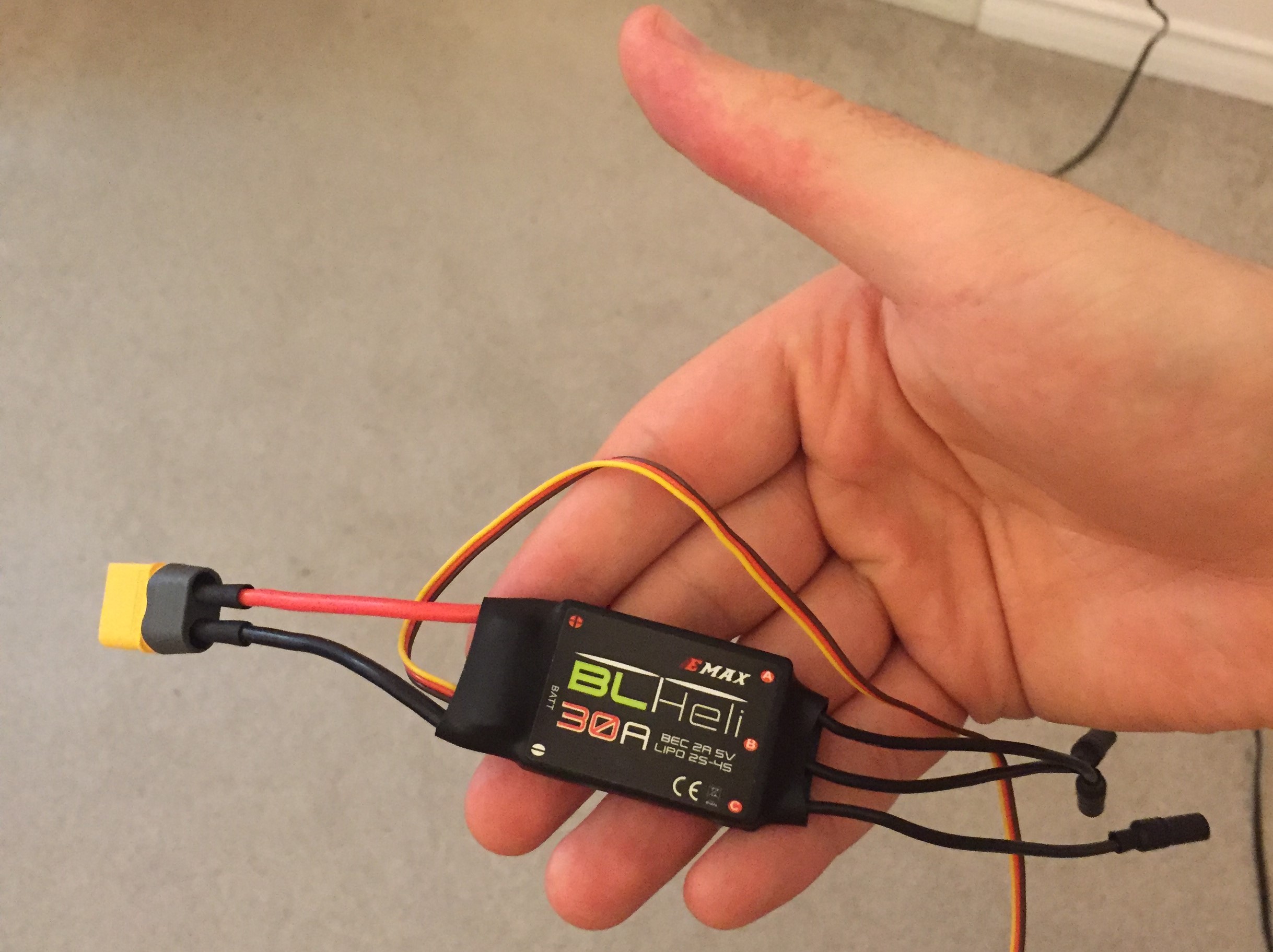
Chosen BLDC Motor
Choosing Power Electronic Components
To start off the project, I chose which motors, speed controllers and battery I wanted to use.
I chose a couple of hobby 360KV BLDC motors and two 30A helicopter speed controllers (for their bidirectional ability).
I ended up choosing to use a 14.8 V 6000mAh battery to power the entire tank.
Choosing Control Circuit Electronics
Before constructing the radio control circuit, I chose which components I wanted to use.
I decided to use Arduino nanos since they are just as capable as an Arduino UNO, but they are much smaller.
For the radio transceivers, I used NRF 24L01 modules, since they are quite popular and have a lot of documentation.
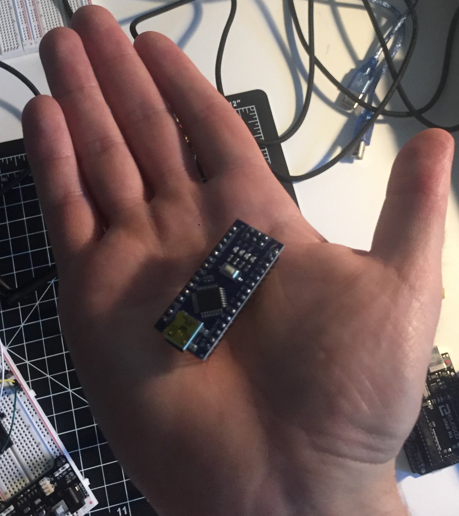
Arduino Nano
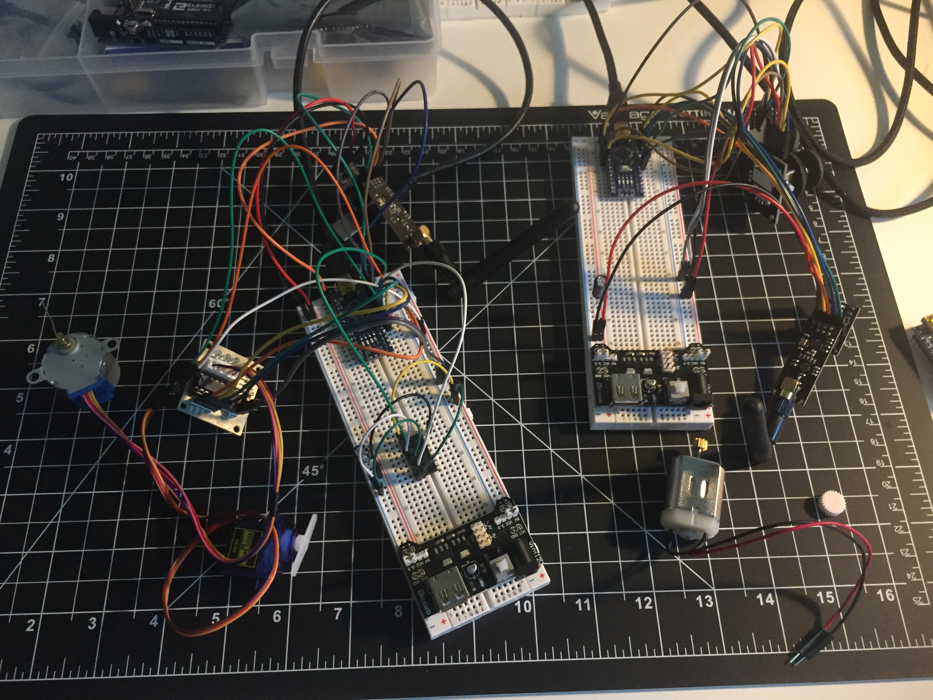
Arduino Radio Control Circuits
Control Circuit
As the next step, I began working on designing the radio control circuit and implementing it using the NRF24L01 modules and Arduino nanos.
I found some basic examples online and read the modules' datasheet to create my own program. I tested it by trying to control a small stepper motor.
I ran into some issues with the signal dropping and the receiver not picking it up again.
To fix this, I implemented a loop that checks whether the signal is detected, and if it is not, it will continuously search for the signal.
Soldering Connections
Now that I had the control circuit working, I began soldering connectors for the motor and battery.
I soldered 6 small connectors between the motor and speed controller for each controller.
I soldered and heat shrinked a power splitting cable that allows the battery to power both speed controllers in parallel.
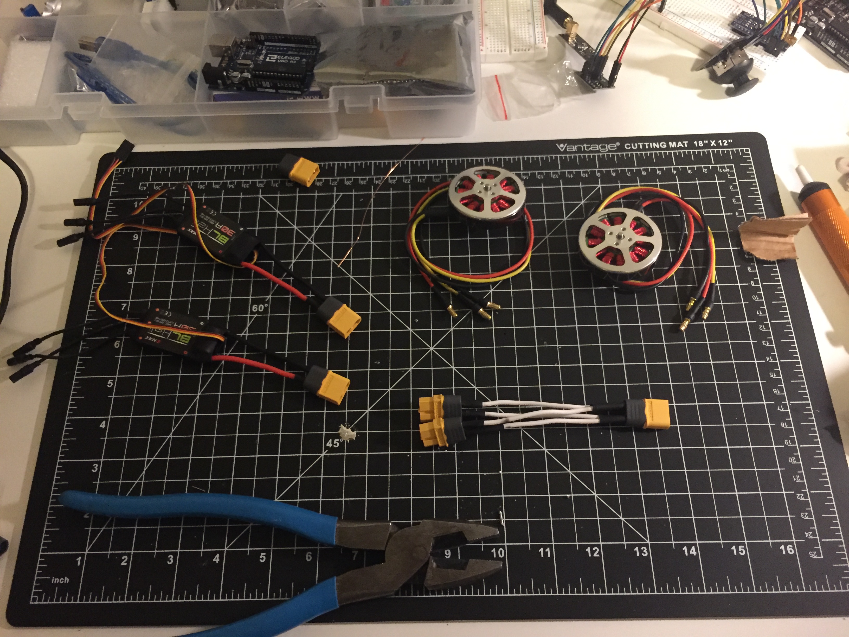
All soldered components
Close-up of soldered motor controller
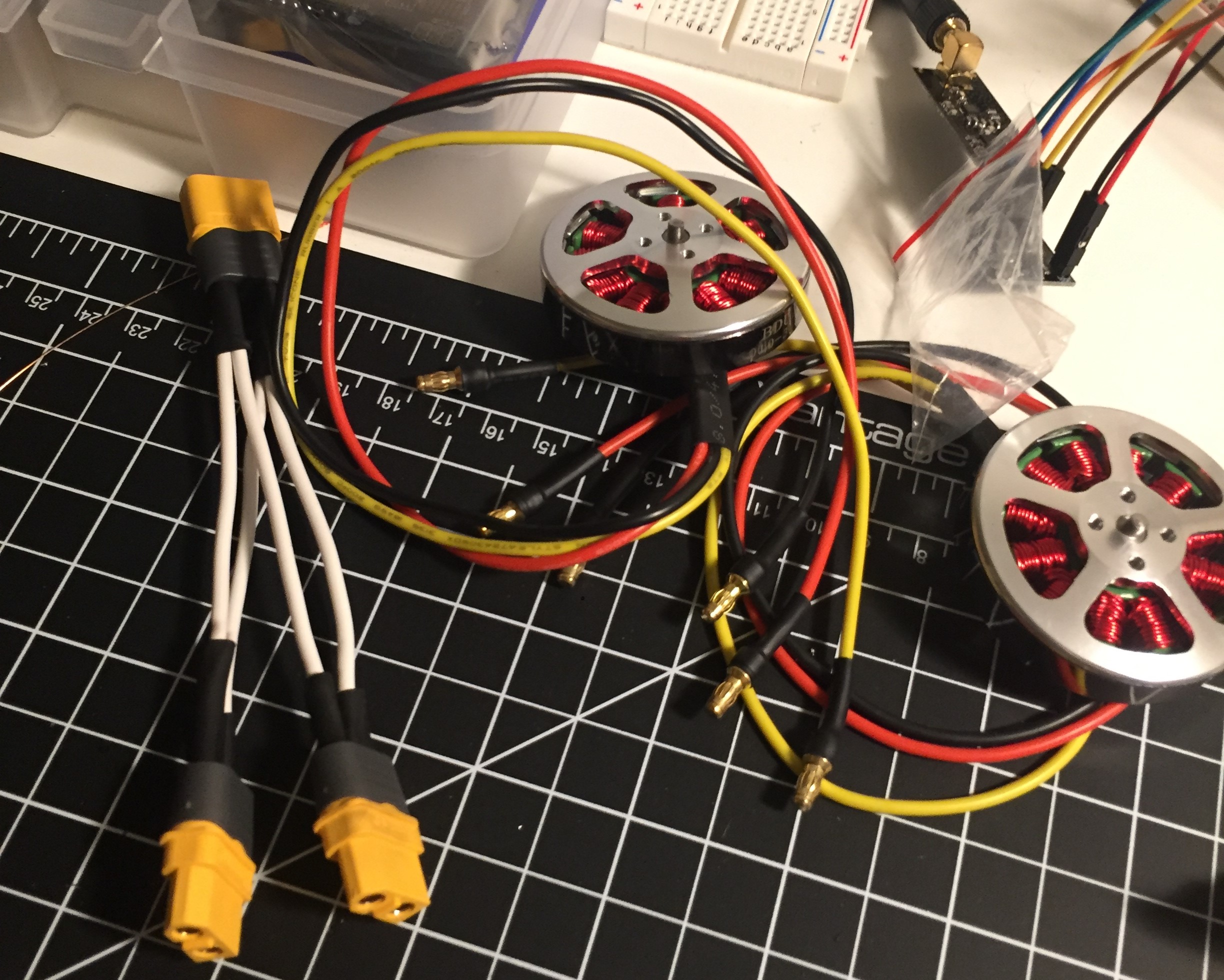
Close-up of battery splitter cable
Testing Motors with Control Circuit
Testing Motors with Control Circuit
To test the motors and to prevent them from flying off my desk due to any issues with the control system, I created and 3D printed testing jig.
After testing the circuit, I found a lot of noise in the radio signal on the receiving side. I solved it by adding a capacitor in parallel with the transceiver's supply voltage and ground on both sides.
When testing the range of the radio, it still worked from 2 floors down in my basement.
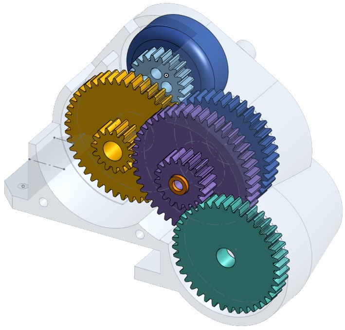
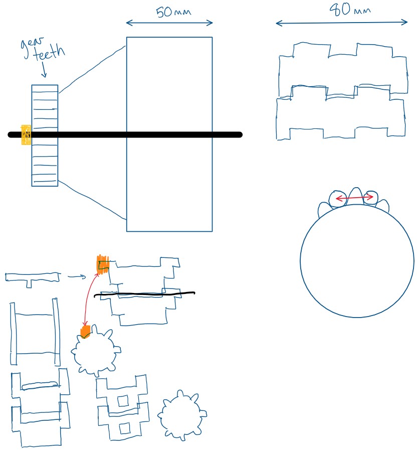
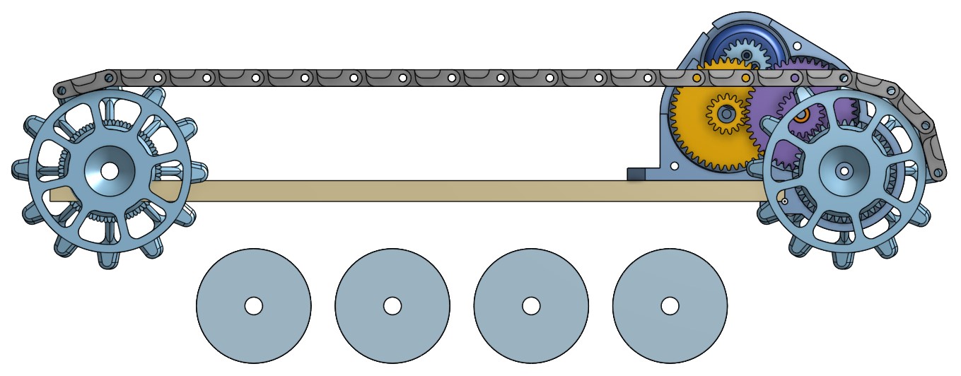
Concepts and Designing of Gear Box
To acheive the required torque and speed from the motor, I needed to create a gearbox with a 40:1 reduction.
I created concept sketches for the layout and dimensions of the gear train, then modelled it in OnShape.
To complete the model, I found some off-the-shelf components (such as bearings and rods) to use.
After designing the model, I 3D printed it and assembled it.
I ran into a couple issues with the friction between the gears. The gears were printed slightly too large, so they were experiencing excessive radial loads.
These issues were fixed by adjusting the size of the gears and by adding spacers between the gear faces.
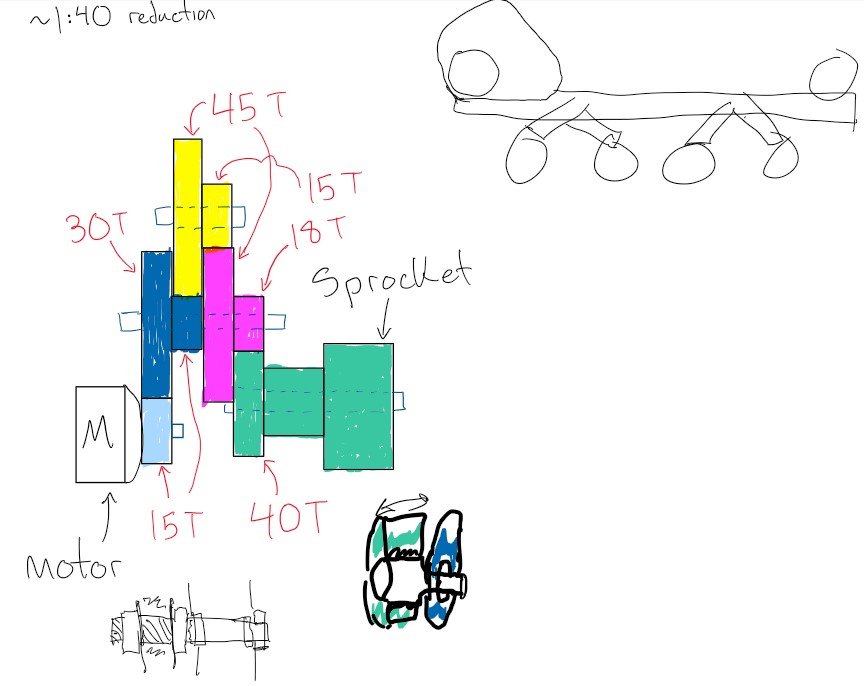
Gear Train Concept Sketches
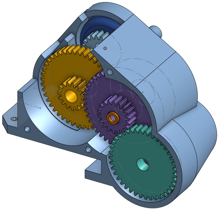
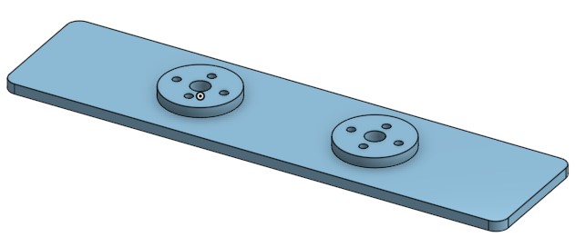
OnShape model of gear box
Invisible enclosure
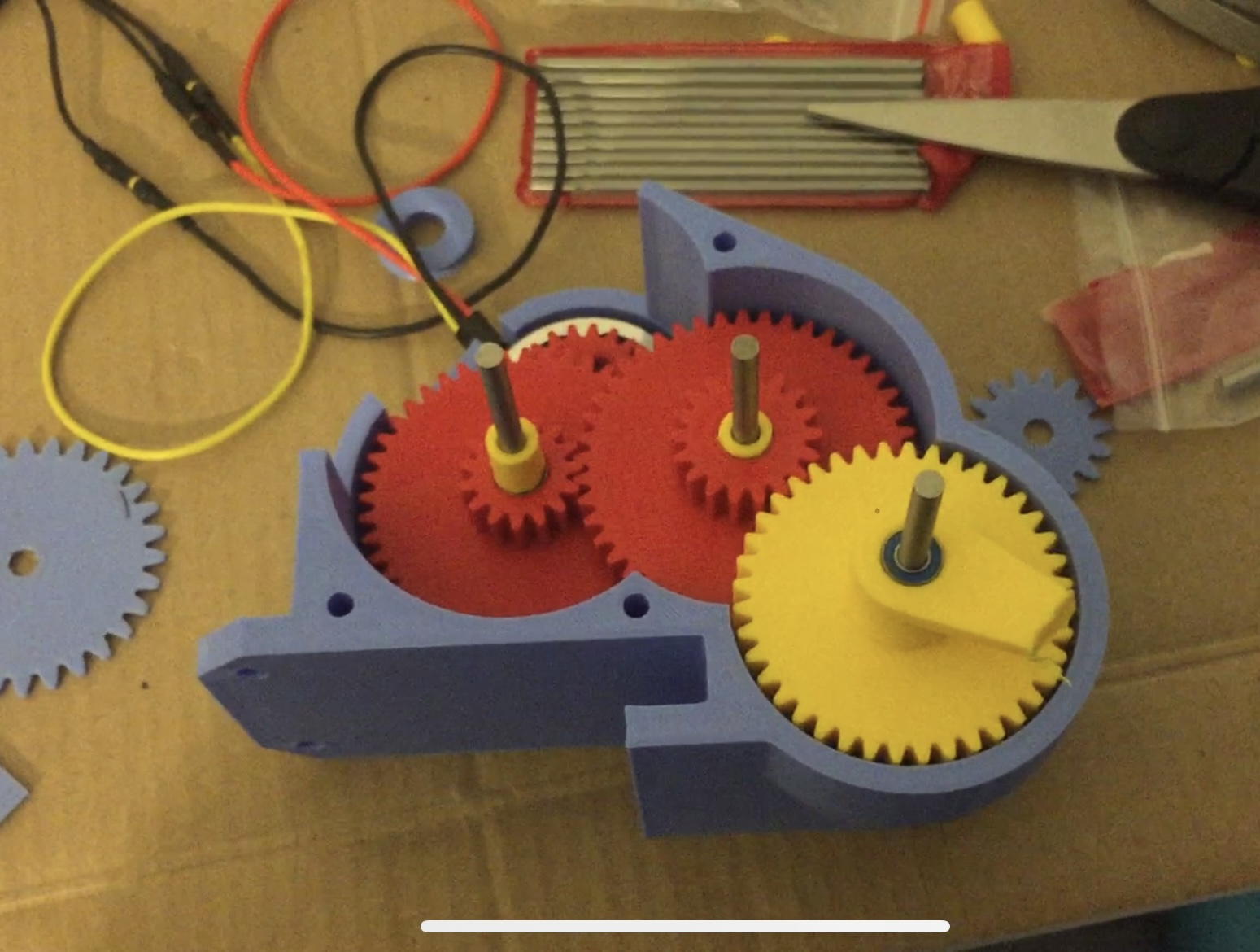
Final printed gear box
Concept sketches of sprocket and tracks
Concepts for Sprocket and Tracks
For the sprocket and track system, I created some concept sketches. The main goals were for the track links to properly mesh with the sprocket, and for there to be enough room to clear the chassis.
I designed and modelled a sprocket and its links in OnShape and 3D printed some prototypes to test how well they meshed in real life.
After the testing was complete, and the links were adjusted to fit properly, I printed 40 links to create a full track .
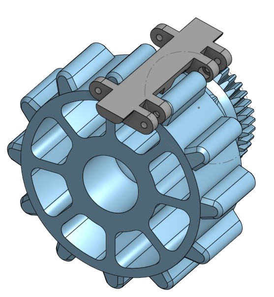
OnShape model of sprocket
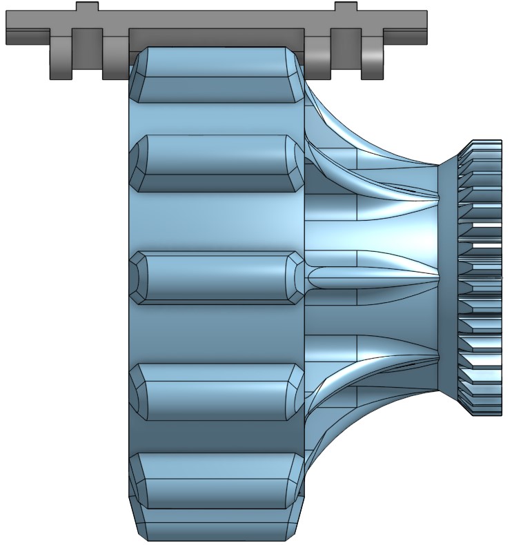
Side view of sprocket
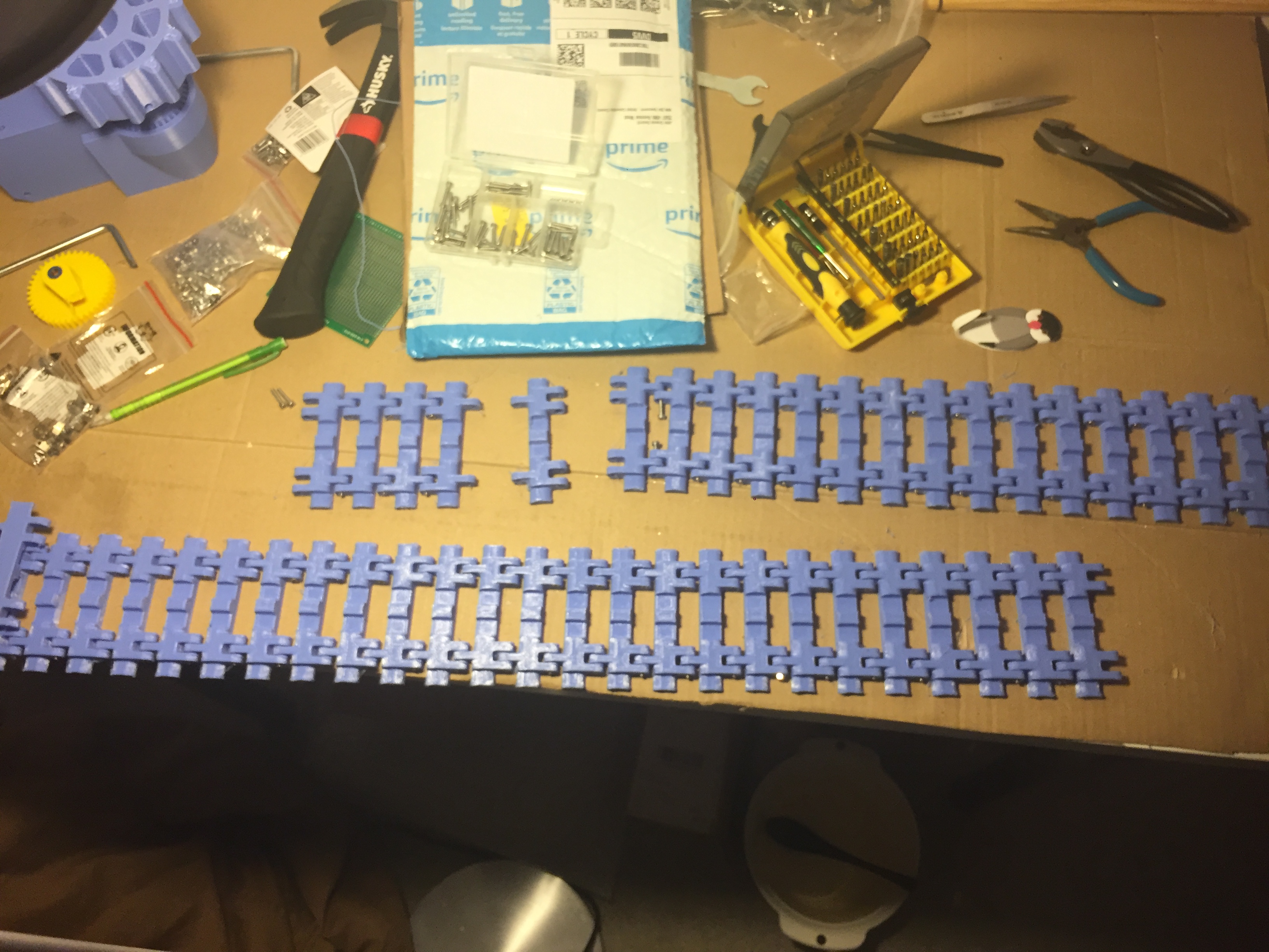
Printed track links
Next Steps...
Since this project has currently been put on hold during the school term, I have a few ideas for the next steps.
I will design a suspension system for the tracks.
I will create a PCB board and a controller for the radio control circuit.
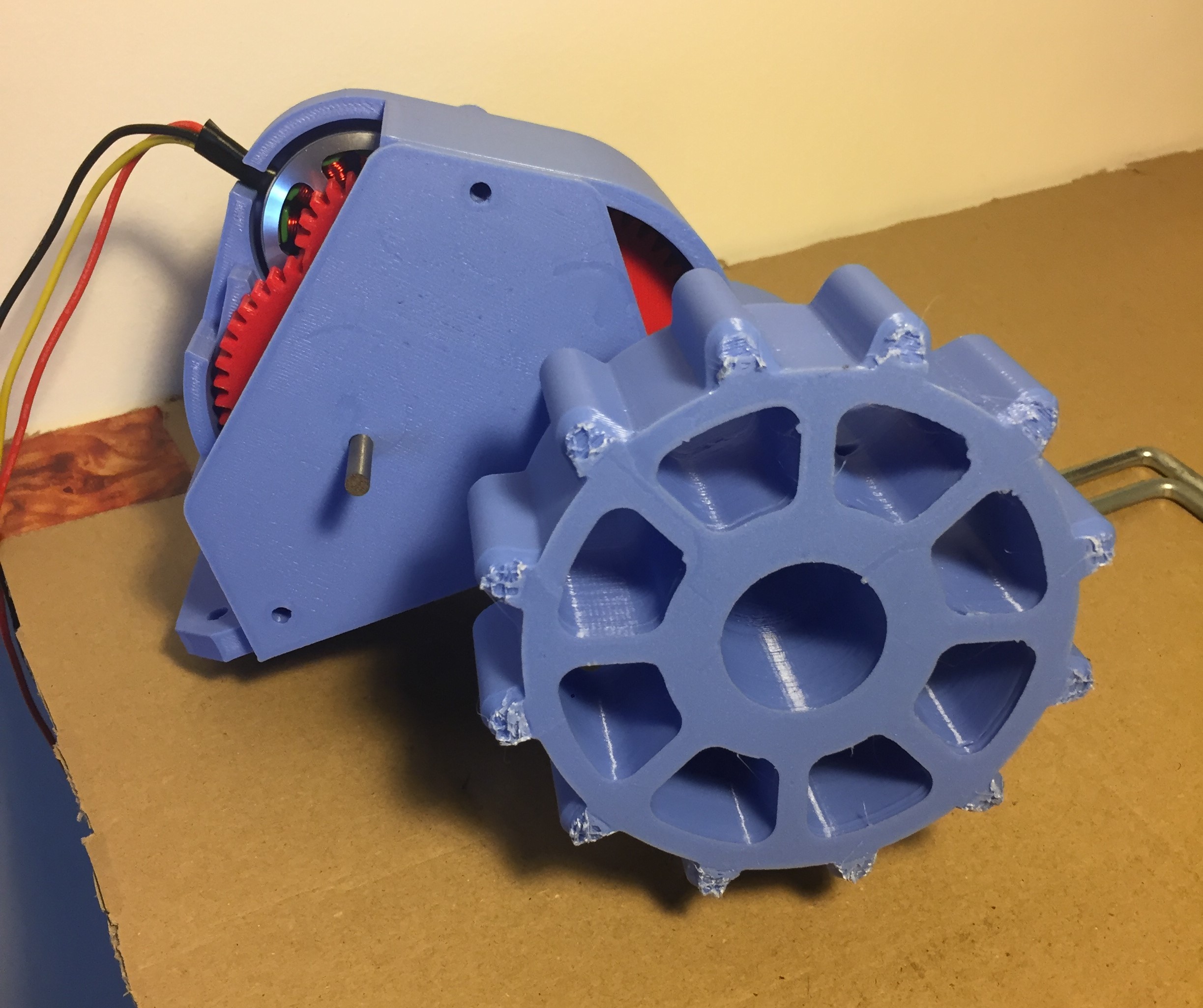
Gear train with sprocket
OnShape assembly of tank so far
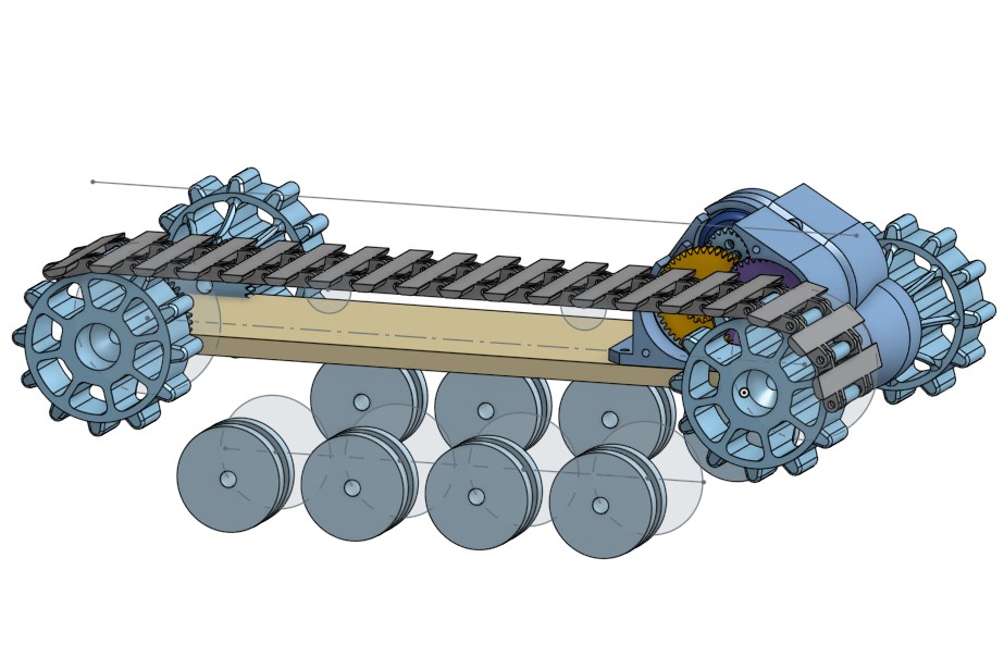
Isometric view of tank model
Final Remarks
This project is in progress.