Solar Car Steering System
September - December 2021
Project Overview |
Developed Skills |
||
|
|
|
|
Objective
This project was part of my machine design course MECH 325 and was done in collaboration with UBC Solar's Vehicle Mechanics sub-team to research and design a steering system that may potentially replace the existing one. Nominal values were provided by the team and a minimum factor of safety of 1.5 was set.
Nominal Design Values
Before designing the rack and pinion system, we split our team of 6 into 3 sub-teams, then collected and assesed our nominal design values for a worst-case max loading scenario, which were:
- 300 lbf external load on the rack
- 300 degrees wheel rotation for a half-rack travel
- Half-rack travel should take 1.5 seconds
- 20 degree pressure angle on the rack and pinion gear
- A minimum safety factor of 1.5 for each component
The following work was done very closely with my sub-team member and we both did the same work.
Rack and pinion gear calculations
Force Analysis
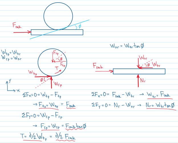
To start off we created free body diagrams of the rack and pinion gear, and used equations from the course to determine the loads.
We determined the radial and transverse loads on the pinion gear, as well as the steering torque that would be transmitted through the shaft.
Calculating the required pinion diameter to achieve the nominal turning time and wheel travel, we found the diameter to be 7/8".
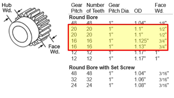
Choosing Closest Pinion Diameter
Looking at McMaster Carr, we determined the closest pinion gear to be a 1" pitch diameter through hardened steel pinion. This pinion would result in a 265 degree required wheel turn.
We proceeded with analyzing the bending and contact stresses for a couple different gear pitches using an excel spreadsheet.
Unfortunately, the 20 tooth pinion fails with a bending stress safety factor of 0.771, and the 16 tooth pinion fails with a bending stress safety factor of 1.1, which is less than our minimum of 1.5.
McMaster Carr 1" pinion selection
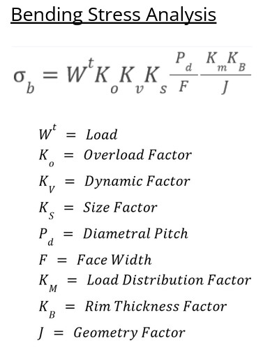
Bending stress formula
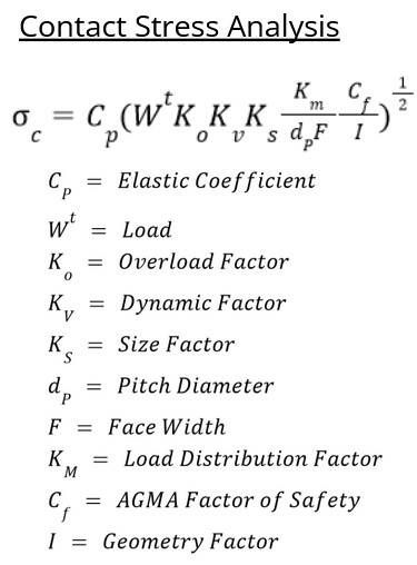
Contact stress calculation
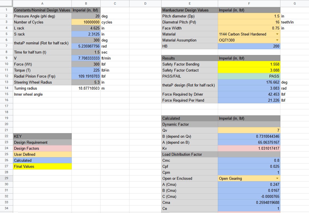
Rack and pinion spreadsheet
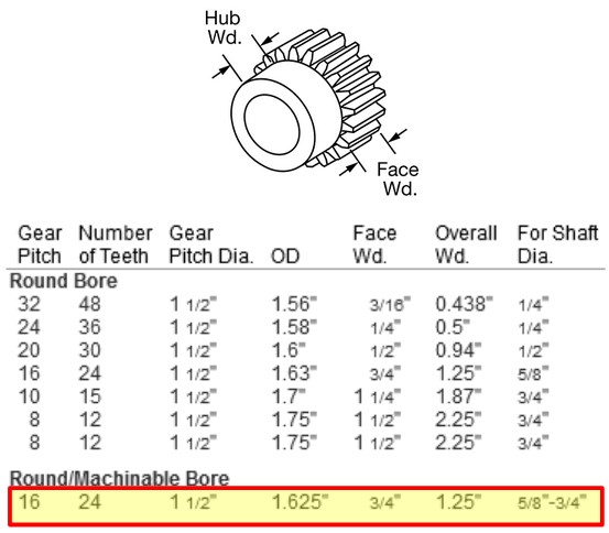
McMaster Carr 1.5" pinion selection
Stepping Up to Next Size
Since the 1" pinion failed, we chose the next closest pinion at 1.5". Using a 1.5" pinion would result in a 177 degree wheel turn, which is still acceptable.
Using the figures and tables from our text book Shigley's, we did our bending and contact stress calculations on the new pinion.
The 1.5" pinion passed with a bending stress safety factor of 1.558 and a contact stress safety factor of 3.088.
Bill of Materials for Rack and Pinion
The pinion in our final design came to $45.13 and the rack came to $33.51, totalling $78.64.
After our section was complete, we gave the pinion parameters and the shaft torque to the shafts team so they could select their parts.
After our entire team had completed our design, we prepared both a formal presentation and report.
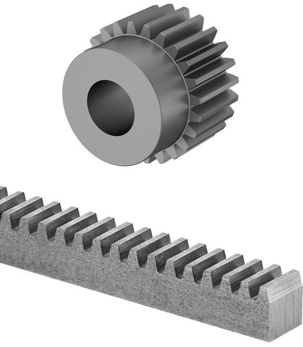
McMaster Carr rack and pinion selection
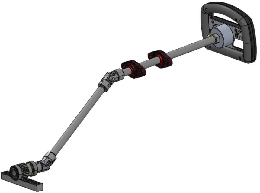
Final SolidWorks CAD design of the system
Final Remarks
After the project was completed, we presented in front of our peers and it went very well. There is not much I would have done differently if I were to do this project again (besides maybe starting a bit earlier in the term).
The UBC Solar Vehicle Mechanics sub-team also said if the funding was available, they would proceed with the design, modifying it where necessary.