MECH 2 RC Rover
January 2020
Project Overview |
Developed Skills |
||
|
|
|
|
Objective
This project was part of my second year mechanical engineering program, where I was put in a team of 6 people, where we had to produce a remotely operated vehicle and compete against our peers. Some information was known about the types of obstacles that we would encounter, but nothing specific. The challange of the project is the motors must be at 100% throttle at all times.
Sketch of tank concept for rover
Concept Generation
First, we started with concept generation and we began sketching out several possible designs for the rover.
We focused on getting as many unique and "out there" ideas as possible to not become tunnel visioned on a single concept.
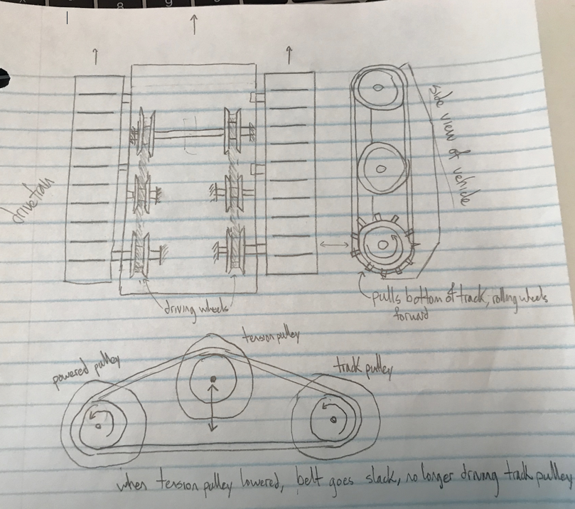
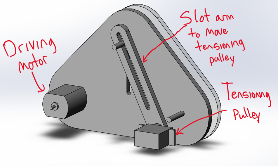
Through concept generation, I came up with an interesting idea for a transmission system which involves disconnecting an idler puller with a servo arm.
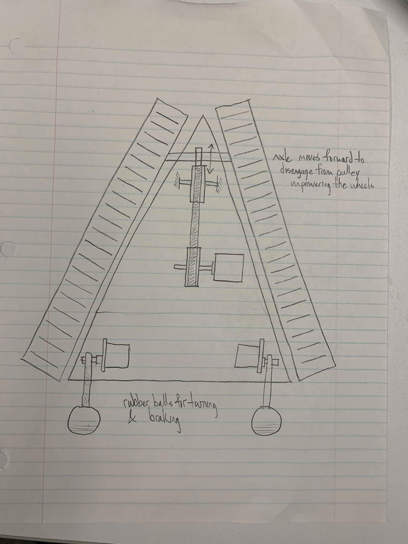
Triangular tank concept sketch
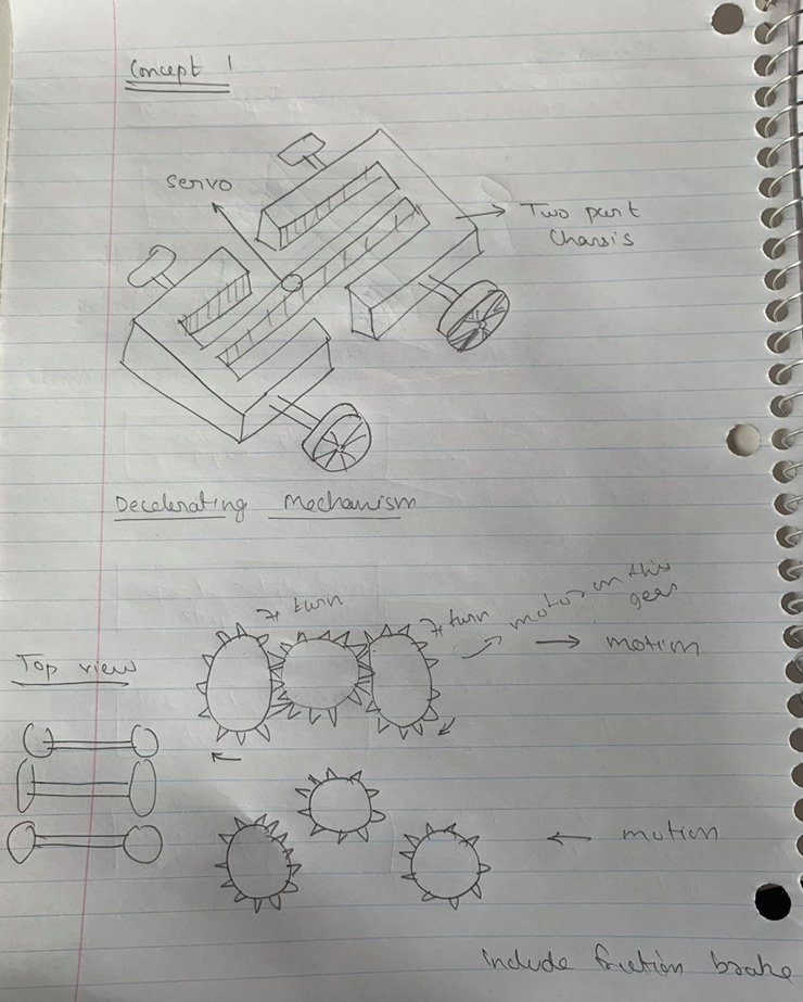
Four wheel center-bending sketch
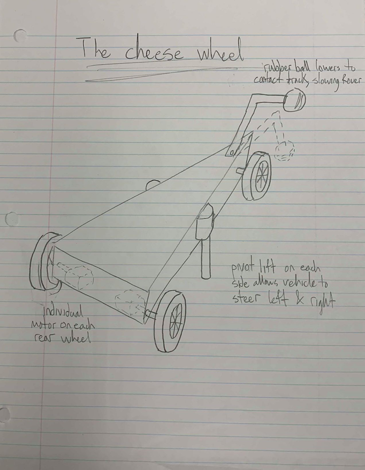
Three-wheeled sketch
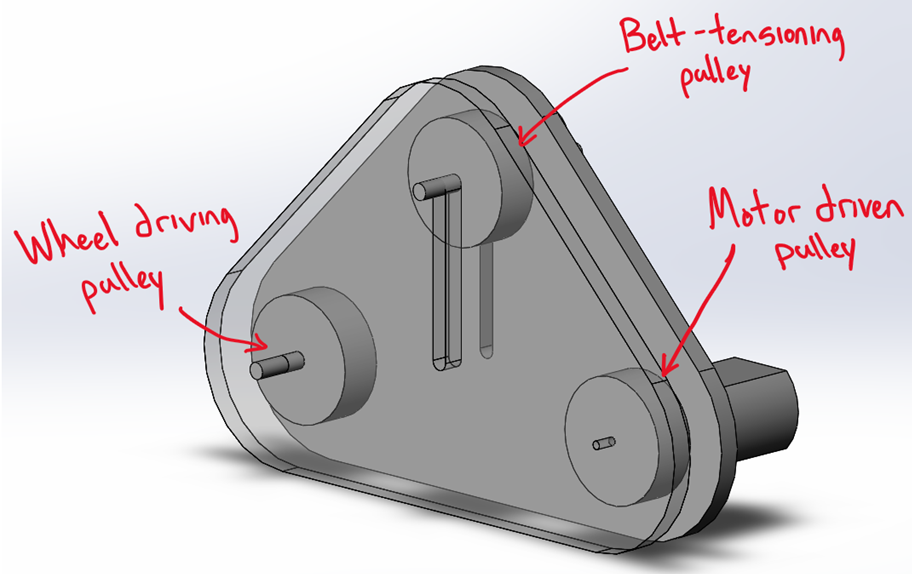
Transmission Concept Modelling
I developed the paper concept I had into a rough model (shown on the right) in SolidWorks to get a feel for how the system would actually work.
I changed the pulleys to have a V-groove in them to better hold the belt and I further developed the concept (shown in pictures below).
Initial pulley transmission model
Back side of initial model
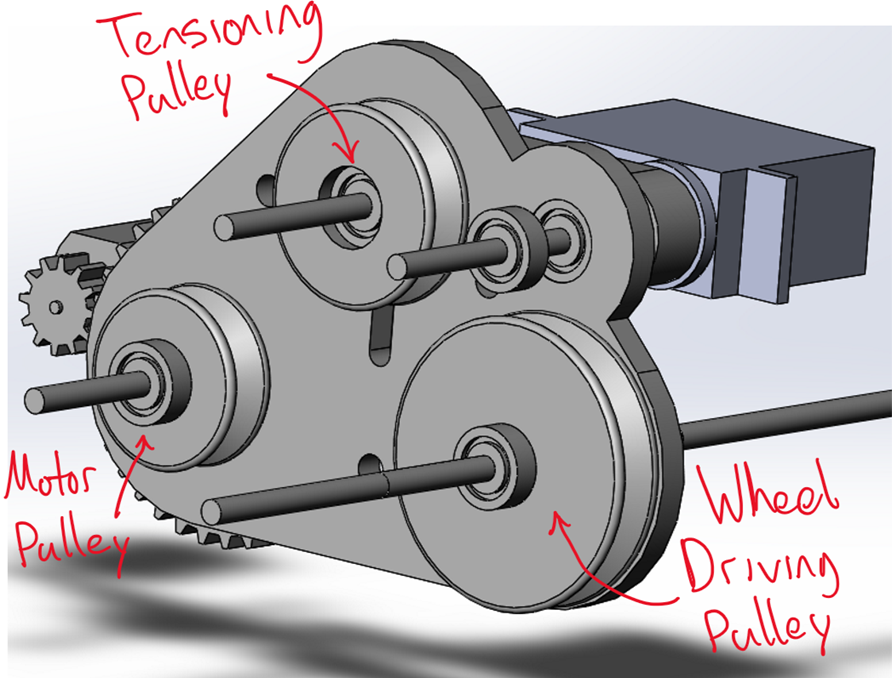
V2 transmission (front)
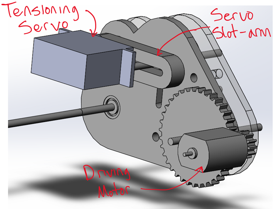
V2 transmission (back)
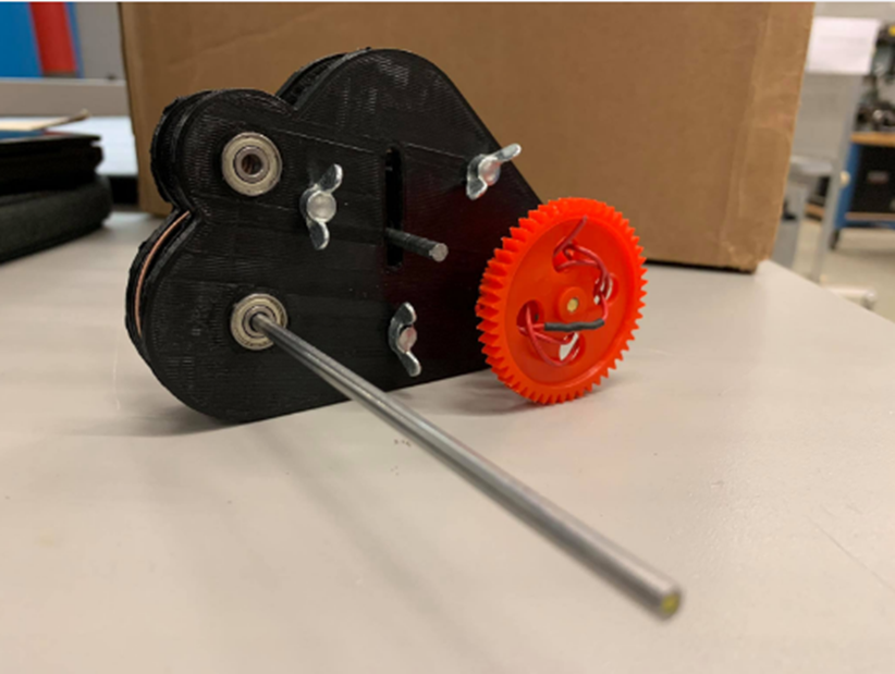
Prototype of V2 transmission
Prototyping the Transmission
Satisfied with the second version of the transmission prototype, I printed out the parts, pressed bearings into the holes, and fastened it together.
Unfortunately, the pulleys had an unacceptably high level of losses due to slipping, which could not be easily or cheaply mended.
I decided to explore a direct transmission system.
Braking Concept
The next problem to tackle was getting our vehicle to stop at the end of the course.
My team came up with an idea to stop the rear axle of the car by jamming an arm into a ratchet and stalling the motor.
I was responsible for developing a model for the concept.
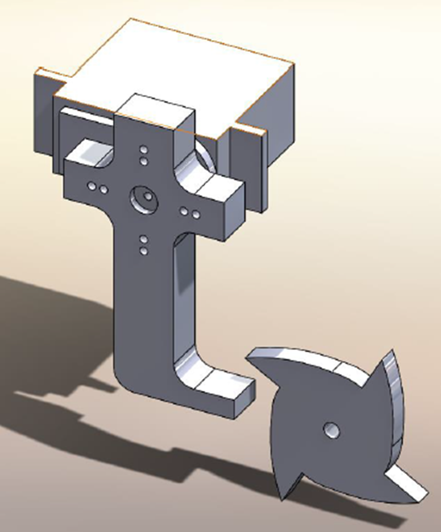
Ratchet brake model
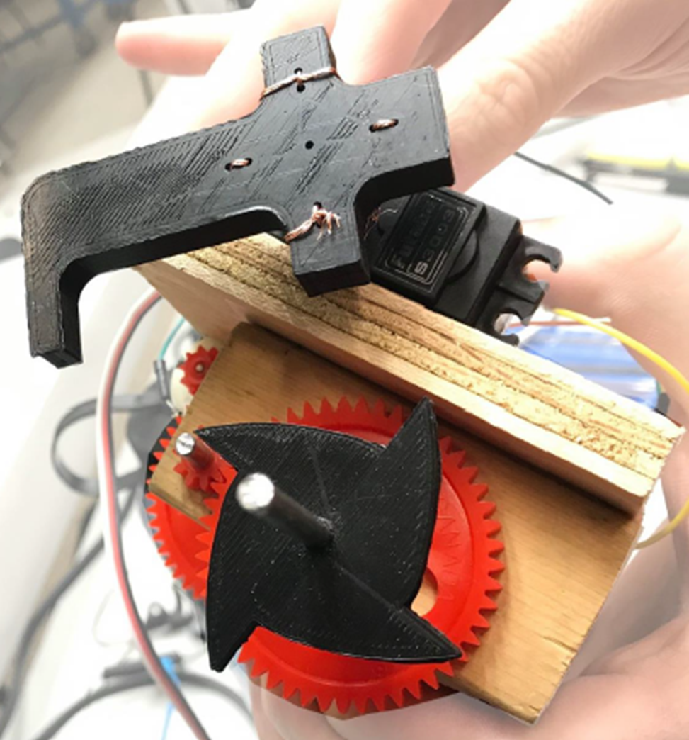
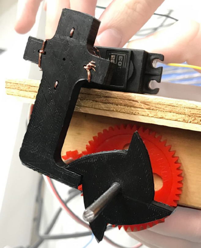
Brake prototype. left: disengaged, right: engaged
Prototyping the Braking Mechanism
Satisfied with the model for the braking mechanism, I 3D printed the mechanism and mounted it on a servo motor to test its effectiveness.
The mechanism was very effective at stopping the car, so we moved forward with it for the final rover.
Final Rover
After the braking and transmission systems were designed, I designed a simple pin-in-slot steering system to use in the rover.
I modelled the entire system in SolidWorks so we could use the model on our poster.
Assembling all of the different systems together, our rover was ready to tackle some obstacles and participate in the competition.
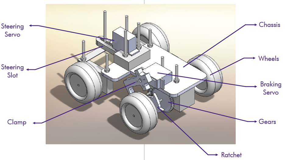
Full rover SolidWorks CAD
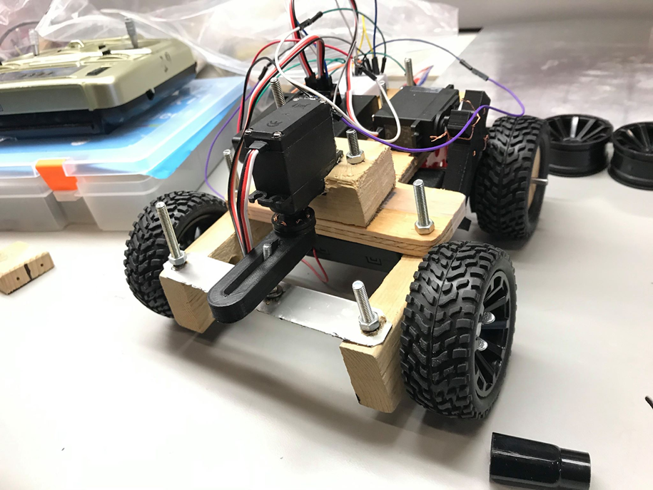
Final rover
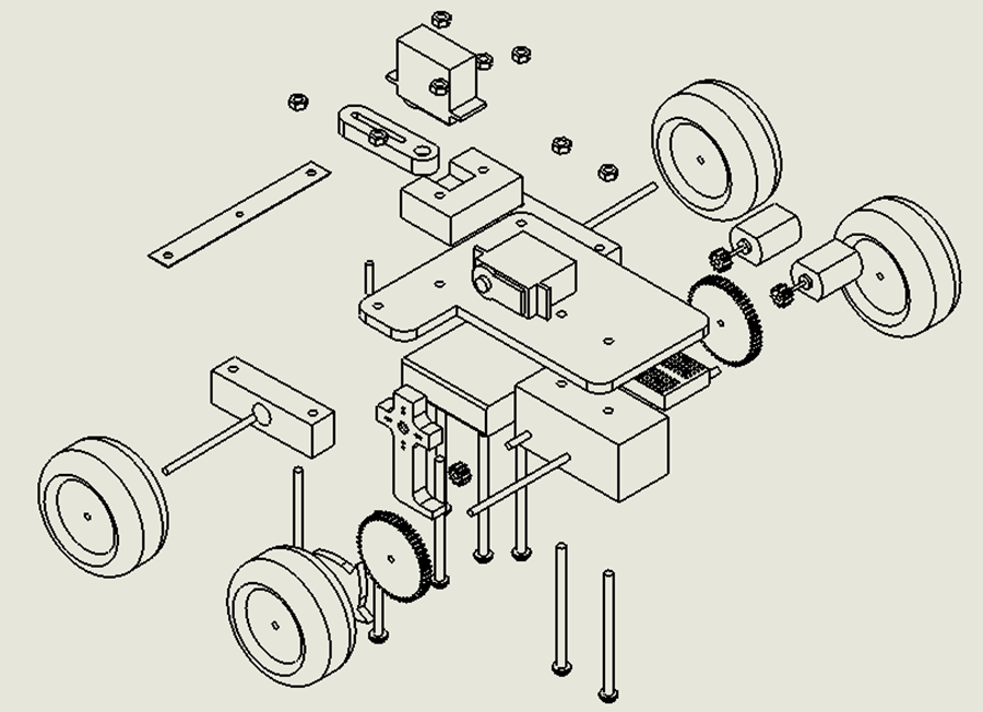
Exploded view of rover
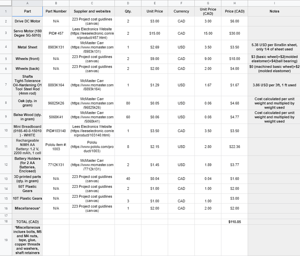
Bill of materials for rover project
Bill of Materials
Throughout the project, I was also responsible for ordering the required parts and keeping track of my team's expenses.
I did this using a bill of materials organized in google sheets, so it could be modified on another machine.
Final Remarks
After the project was completed, our rover failed spectacularly - as you could probably tell from the state of the final version.
That being said, there are quite a few things I would have done differently, with my current knowledge of mechanical engineering.
I would not rely on stalling the motor to stop the rover, as this can damage the motors and the gears. I would instead use some sort of servo arm to lift the driving wheels off the ground.
I would have put more time into designing the steering system and testing the rover before competition (though the timeline was extremely tight).