Portable Printer
January 2021 - Present
Project Overview |
Developed Skills |
||
|
|
|
|
Objective
This project was done as part of my design team, UBC Rapid. Our goal was to create a portable 3D printer that is light and small enough that a student or maker could bring it with them wherever they go.
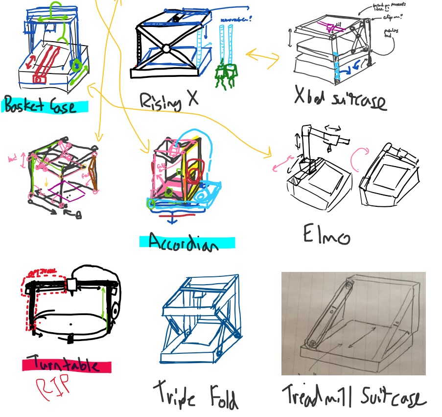
Portable printer concept sketches
Concept Generation
To start off the engineering process, we generated as many concept sketches as possible to have a broad selection of concepts to choose from.
Several of the concepts seemed promising, so we moved on to the evaluation stage for each concept to eliminate impractical ones.
Eliminating Concepts
Using our list of generated concepts, we went through each and eliminated those which would not work, or that we were not prepared to build.
After the winnowing process, we moved on to scoring and ended up choosing a "hanging X" concept.
This concept has a scissor lift that suspends the build plate below the XY axis gantry.
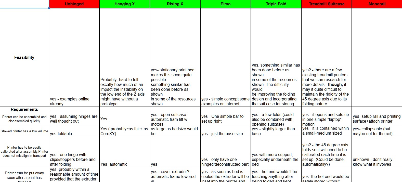
Winnowing chart
Splitting Into Sub-Teams
Before starting work on the printer itself, we split the team up into 4 sub-teams:
- The X-bed team (Lead by me)
- The core XY team
- The electronics team
- The housing team
The following work was done very closely with my sub-team member and we both did the same work.
Portable printer V1
Modelling the Scissor Mechanism
The initial steps were to create a very rought model of the printer, to visualize the mechanism (none of the dimensions are accurate).
Once the first version was produced, two quick iterations were made, taking into account the proper dimensions, how the motors will be mounted, and how the build plate will be held.
Portable printer V2
Portable printer V3
Sizing and Dimensioning Components
With the size of the build plate set, I chose some off-the-shelf parts that will be used, and began accurately modelling the different parts of the printer.
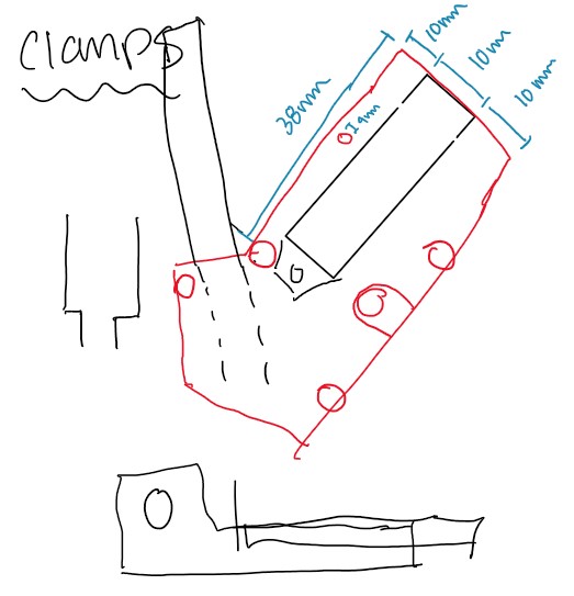
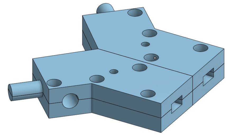
Using a SolidWorks model of our chosen servo motor, I designed a motor mount to hold the motor in position (shown below).
I began measuring our chosen base plate and creating clamps to attach it to the x-arms (shown below).
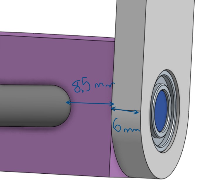
X-arm connection
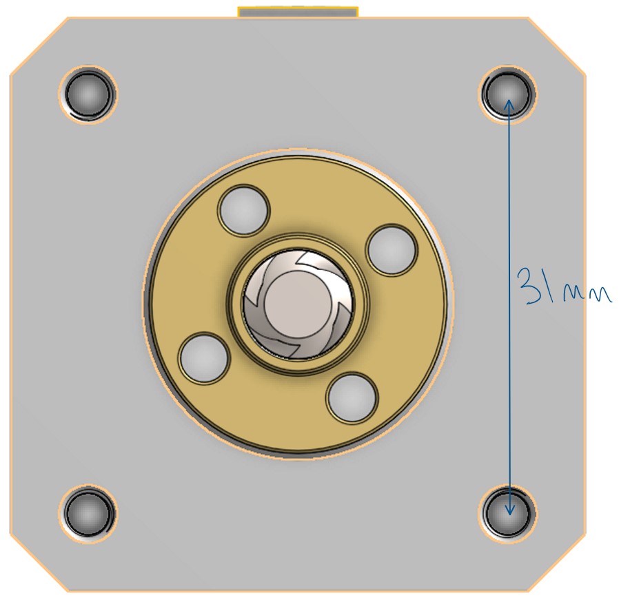
View down threaded rod
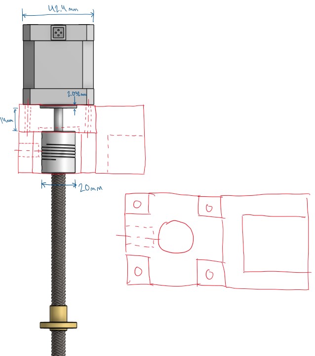
Sketch of motor mount over servo/rod
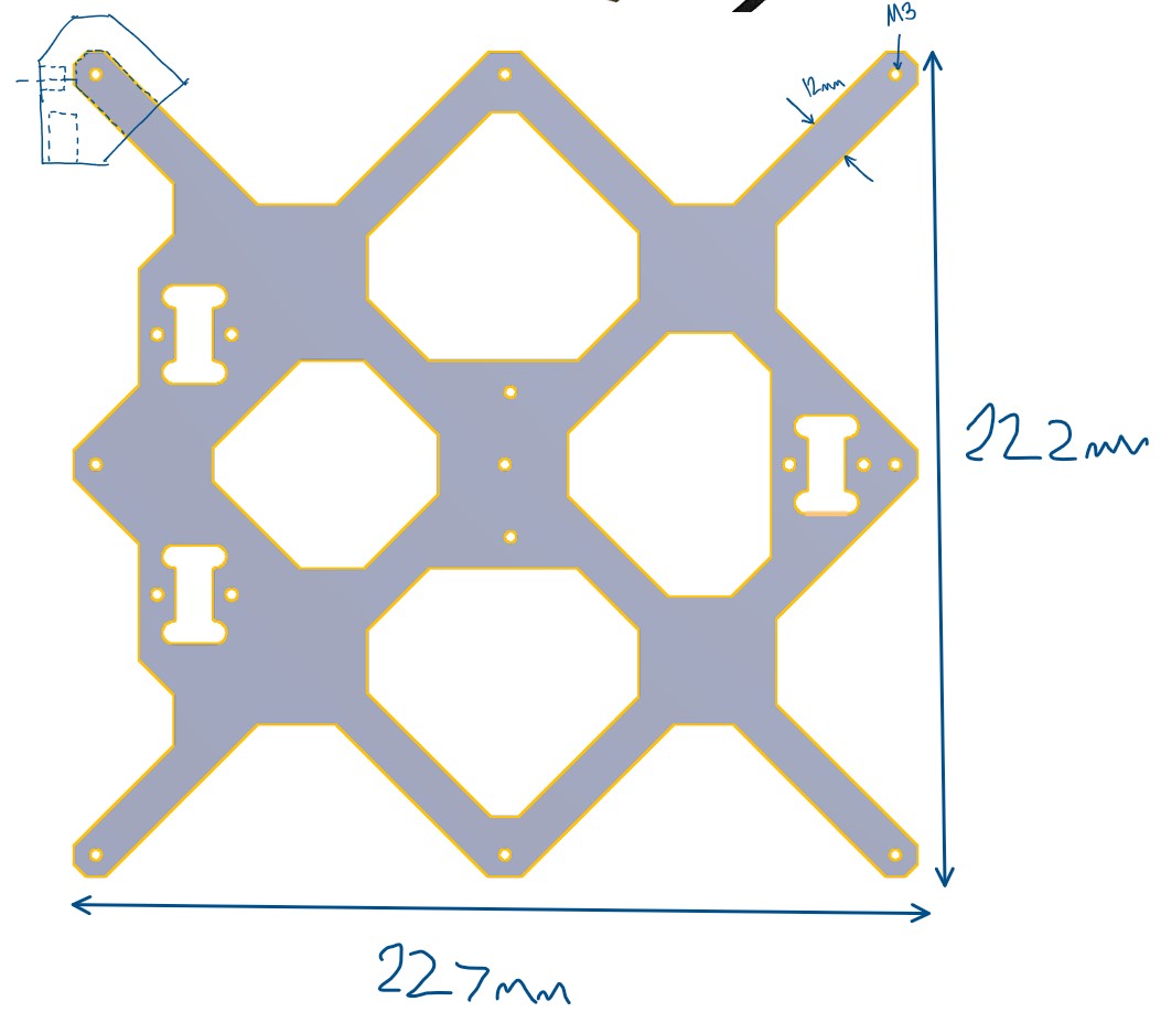
Model of our base plate
Portable printer V4
Modelling Version 4
With V4 of the printer modelled, two members joined my team, and we began discussing improvements and changes to the design and beginning to manufacture a prototype.
I worked collaboratively with one of my team members to design a printable base clamp.
Sketch of base new clamp
OnShape model of base clamp
First Physical Prototype
Now that we have created a physical prototype, there are some problems with our design that we had not previously considered.
The threaded nuts to not sit still on the threaded rods, causing a lot of play in the build plate.
Though the prototype did prove the concept works, as it can be actuated up and down easily.
Prototype moving up and down
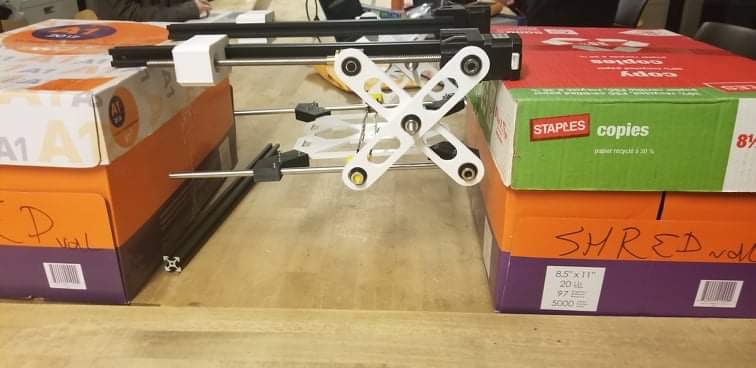
Prototype mounted between two boxes
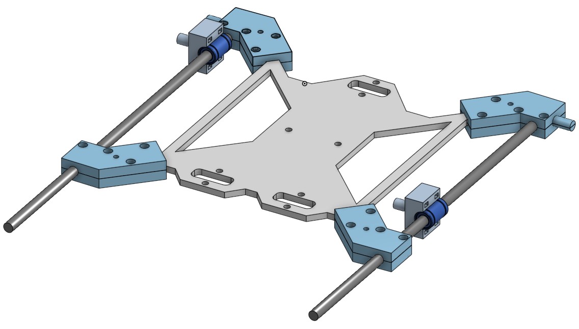
OnShape model of base plate with new clamps
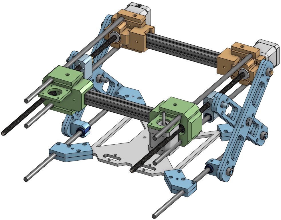
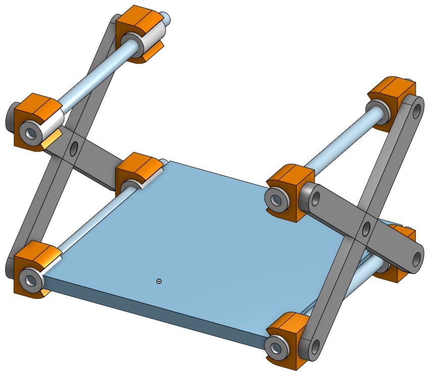
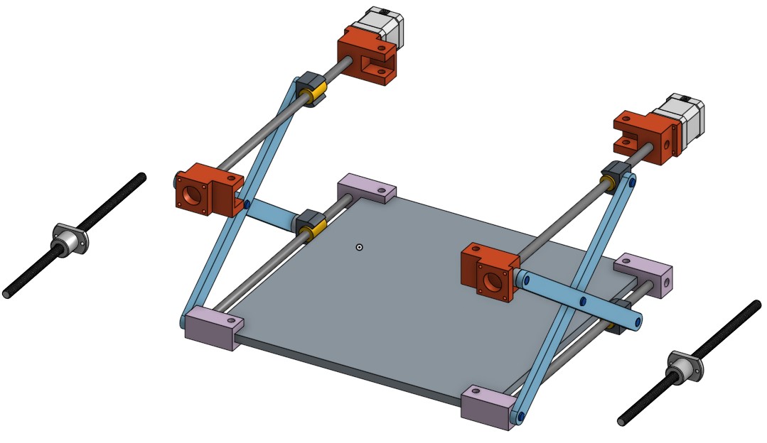
Portable printer V6
Modelling Version 6
After testing the first physical prototype of V4, a V5 model was started, but it was not the direction we wanted to go, so we went on with V6.
The largest changes in V6 were adding two extra rods on each side of the printer. One rod prevented rotation of the threaded rod clamp, and the other serves as the Y-axis rod for the core-xy assembly.
A couple of other notable changes are: changing the threaded rod clamp, sandwiching the x-scissor bearings to prevent them from being pushed out, and including structure for core-xy system.
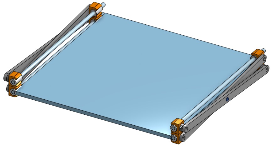
Second Physical Prototype
Now that we have a second physical prototype, we verified that all our problems with V4 have been resolved.
The extra rods add a lot of rigidity to the system and prevent unwanted movement, while still being compact.
Now the core-xy team can start implementing their system to the scissor bed system.

Second Prototype
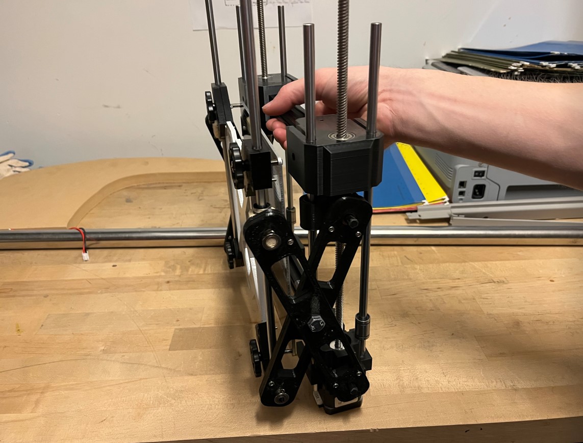
V6 prototype side view (folded)
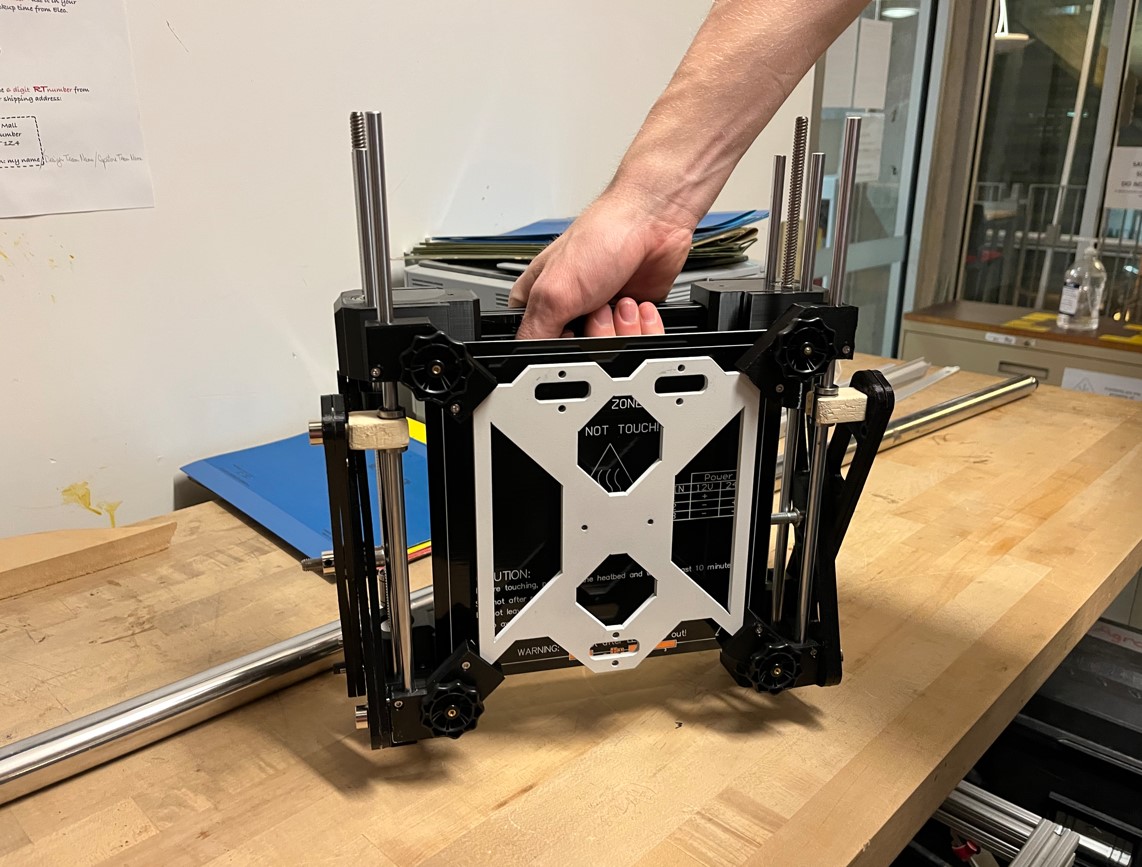
V6 prototype bottom view (folded)
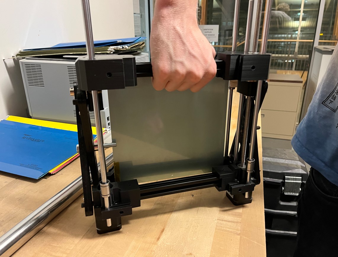
V6 prototype top view (folded)
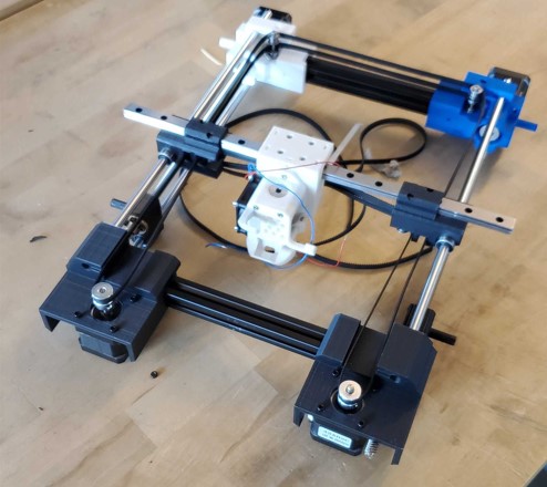
V6 prototype top assembly with core-xy installed
Final Remarks
This project is in progress.