LED Bike Lights
September 2021
Project Overview |
Developed Skills |
||
|
|
|
|
Objective
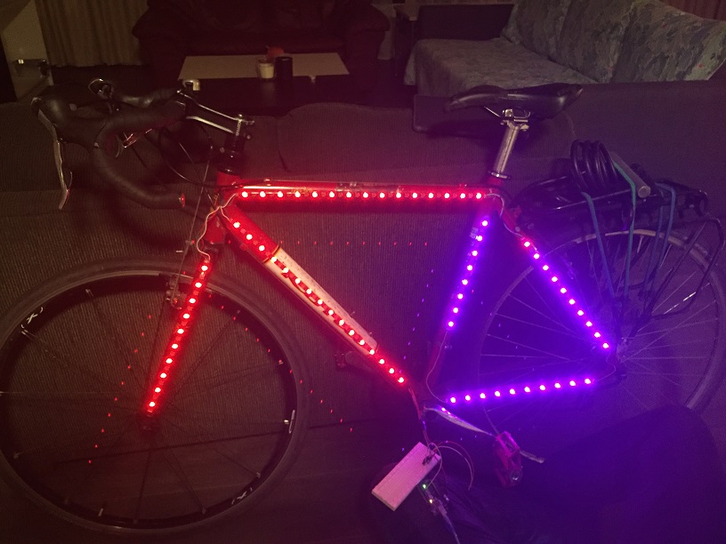
With this project, I wanted to make my bicycle stand out a bit more while riding it around, and to greatly improve safety and visibility while riding at night.

Testing LED strips
Testing the LEDs
First, I started by testing out the LED light strips to see if they worked properly, and to test communicating with them.
I researched the documentation and libraries required to communicate with the LEDs, then I wrote a small arduino code.
The lights worked properly, but there was an issue with the USB port not being able to provide enough power, so I limited the lights to 1/3 brightness.
Cutting the Lights to Length
The strips were held against the frame of the bike and cut to length along the soldering lines.
I zip-tied the strips to the frame to get a feel for how the lights would actually sit on the bike and how long the jumper wires would need to be to connect the strips.
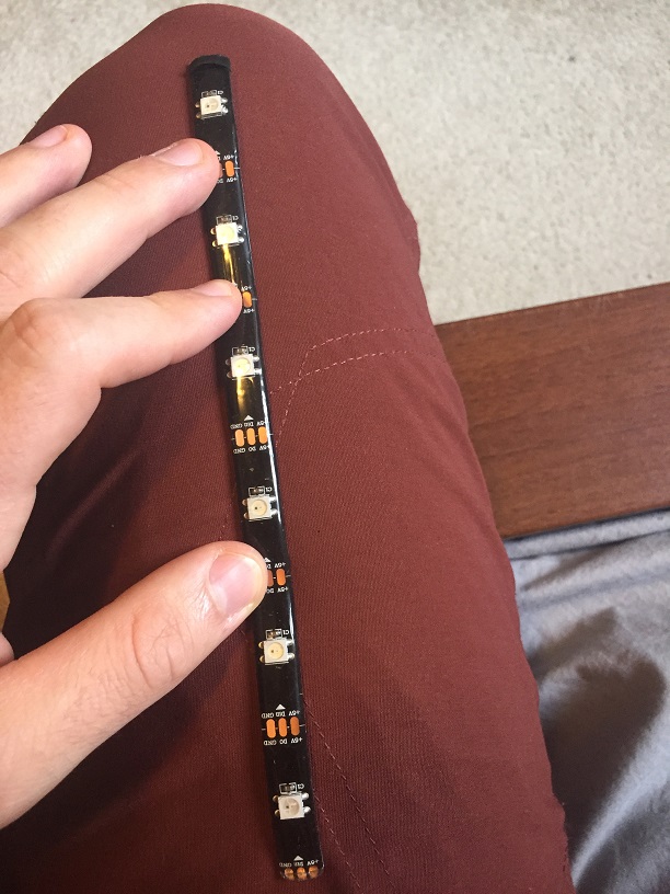
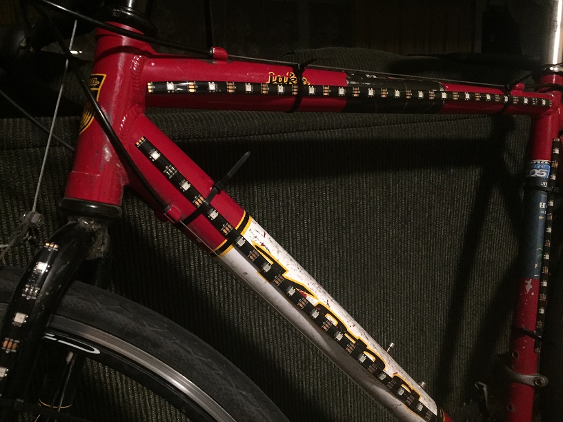
left: cut strip, right: strips zip tied to frame
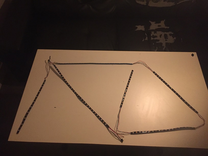
LED strip layout
Soldering the LEDs
After measuring the lengths of wire required to connect each strip, I cut some wires to these lengths and began soldering the strips together.
The connection at the fork was especially tricky, as it had to be strong enough to withstand repeated wear from turning the wheel, so a bit of extra wire was added.
After the soldering was completed, the strips were laid out how they would sit on the bike as one final check.
Mounting the LEDs
Mounting the LED strips on the bike was quite difficult, as the strips needed to be lined up perfectly on the first try and they could not be bent left or right.
The bike was wiped down with a wet towel then dried. After this, the tape cover was peeled off the backside of the strips, and they were mounted one-by-one.
To ensure the strips would not fall off after riding for a while, electrical tape was wrapped around the ends of the strips and the frame.
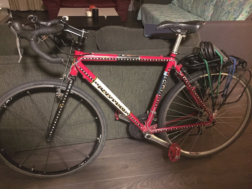
LED strips on bike
Testing strips with a breadboard
Testing the Set-Up
After mounting all the strips, a quick Arduino code was prepared with a function to control the lights and a small circuit was built to test everything.
Amazingly, the entire set-up worked perfectly on the first try.
Now the only thing left to do was design and fabricate a housing to enclose the Arduino/battery and rigidly mount them to the frame.
Designing and Printing the Housing
I measured the Arduino and the battery I would be using, then I created a sketch for the housing.
After creating a sketch, I modelled the housing using Onshape and printed it out. After printing the housing, I realized a mistake with the height dimension, preventing the battery from fitting inside.
I changed the dimensions that were causing issues and adjusted the design to look a bit better, then I printed it. It fit the Arduino/battery and the frame perfectly.
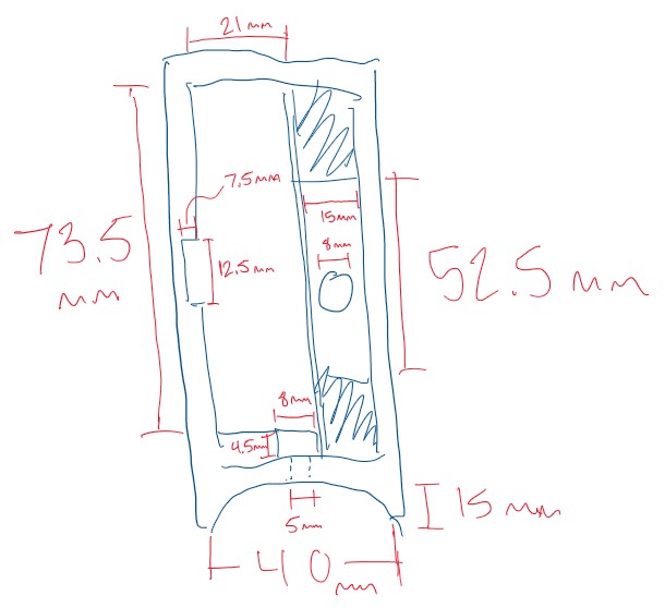
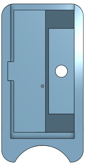
Sketch of the housing
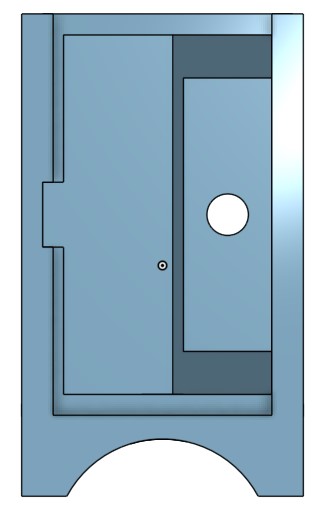
V1 of the housing
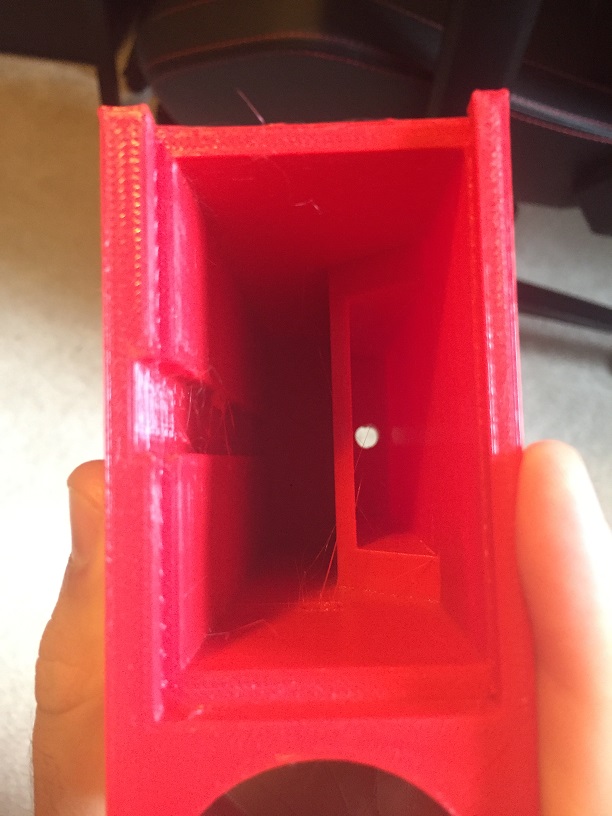
Print of V1 housing
V2 of housing
Running lights at night
Bringing it All Together
With all the pieces completed, they just needed to be connected together to complete the project.
After everything was mounted, any electrical connections were further waterproofed using tightly-wrapped electrical tape.
All thats left to do now is to ride my bike around and test how well the connections hold up under normal riding and bump conditions.
Lights on at night
Riding at night with lights
Final Remarks
Firstly, I would have someone help me while soldering the strips, as it was quite difficult to hold the strip, the wire, and the iron by yourself.
I would work out how to use an external powersupply that can supply a larger current, so I could run the LEDs at full brightness.
I would have taken more care when dimensioning the housing to that I would not have to design another version.