Cell Stretching Device Capstone (Will Add More Info)
September 2023 - April 2024
Project Overview |
Developed Skills |
||
|
|
|
|
Objective
This project was my capstone in my last year of my Mechatronics Engineering degree at UBC. The objective of this project was to work with the UBC Microelectromechanical Systems (MEMS) lab, as well as the BC Children's Hospital to design and fabricate a device for maturing human heart cells through cyclic stretching, as well as the ability to image the process under an inverted microscope.
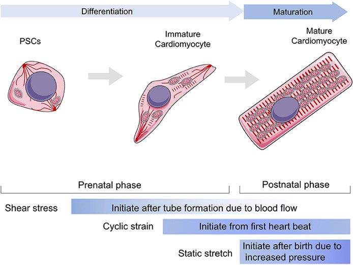
Heart Cell Maturation
Brief Background
The UBC MEMS lab has requested a device that can stretch human heart cells and replicate the human heart environment while allowing the cells to be imaged.
This will allow the lab to mature freshly differentiated heart cells and observe the maturation process to ensure smooth stretching.
The MEMS lab will also be able to study the stress response of the heart cells in detail.
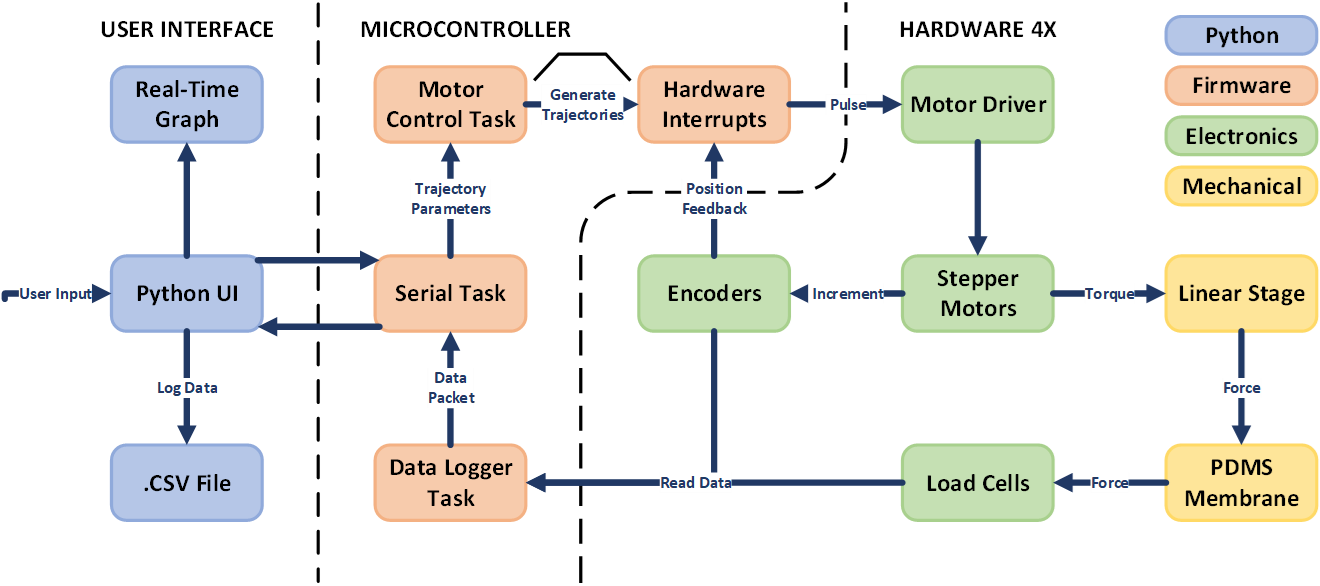
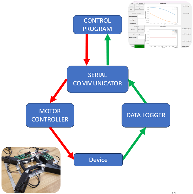
System Overview
The general overview of the system is shown in the flow chart below.
On the Python control program side, the user gives input to send parameters to the MCU and also to receive logging data from the sensors to record and display in real-time.
On the firmware side, the MCU is running FreeRTOS with 3 tasks running.
On the Electrical side, there are the encoders, load cells, the stepper motors, and their drivers.
On the mechanical system side, there are the linear stages and the PDMS membrane.
System Overview
Mechanical Design
The device had compatibility constraints where it had to fit with the existing microscope and environmental control unit (ECU) pieces.
The device needed to have independent stretching control on each axis of the PDMS membrane, with an extreme importance placed on precision.
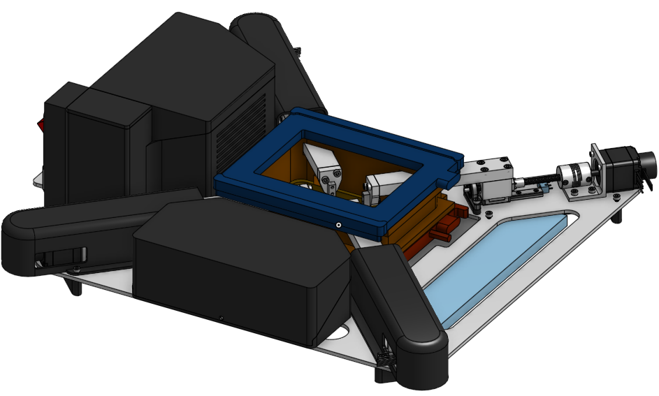
CAD Rendering of Final Device
Linear Stage Design
The linear stage uses a linear rail with a linear carriage, an ultra precision lead screw, a flange mount bearing, and a flexible coupling.
On top of the linear carriage, a block is mounted. On this block a long strut that enters the ECU chamber is attached.
At the end of this strut, a load cell is fixed, which has the grippers for attaching to the membrane mounted on the end.
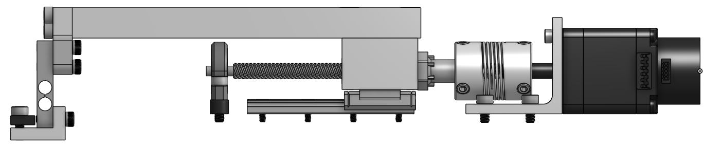
Linear Stage Right View
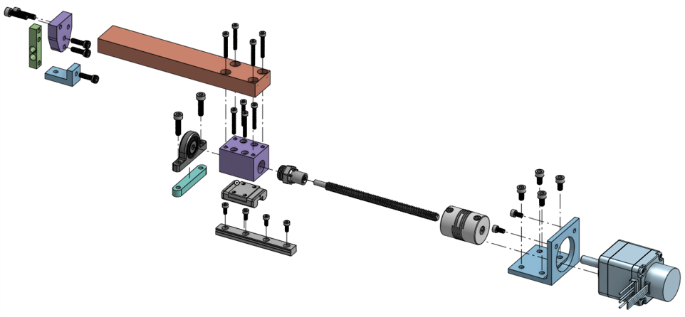
Linear Stage Exploded View
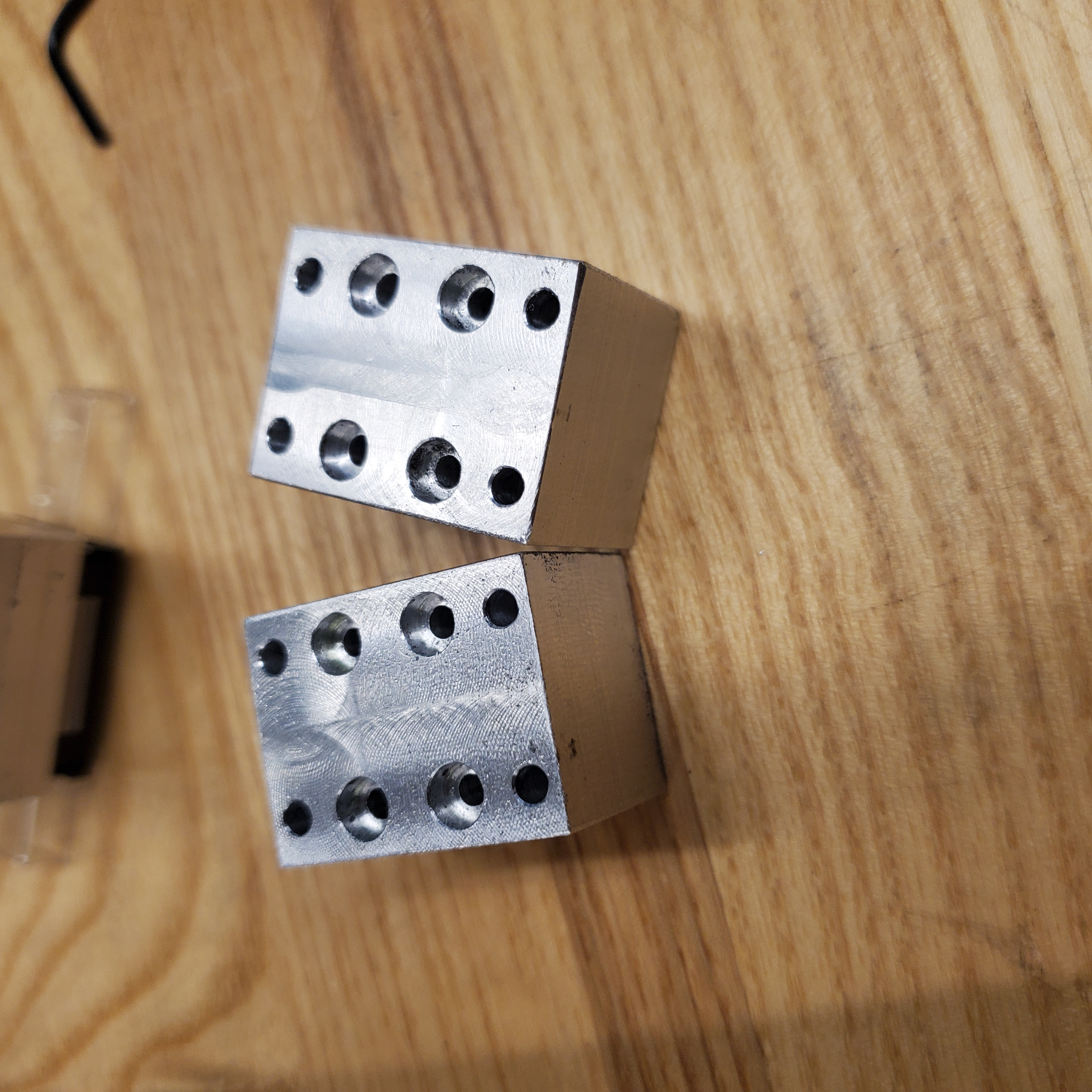
Machined Carriage Blocks
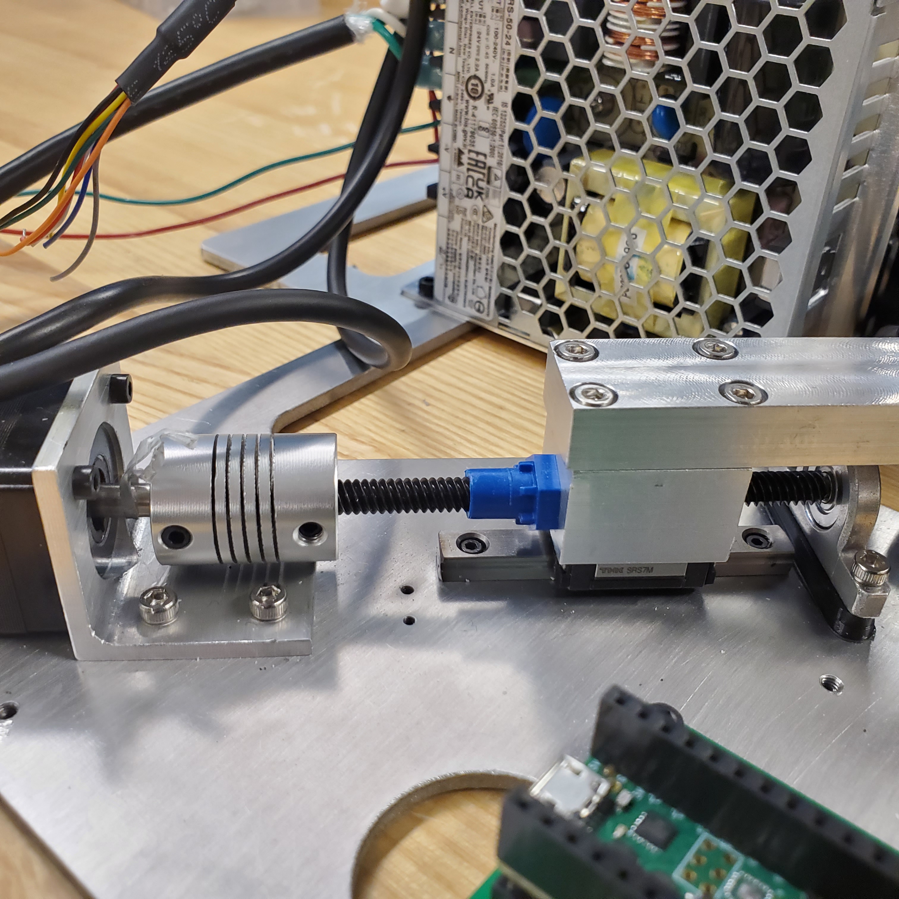
Linear Stage Assembled
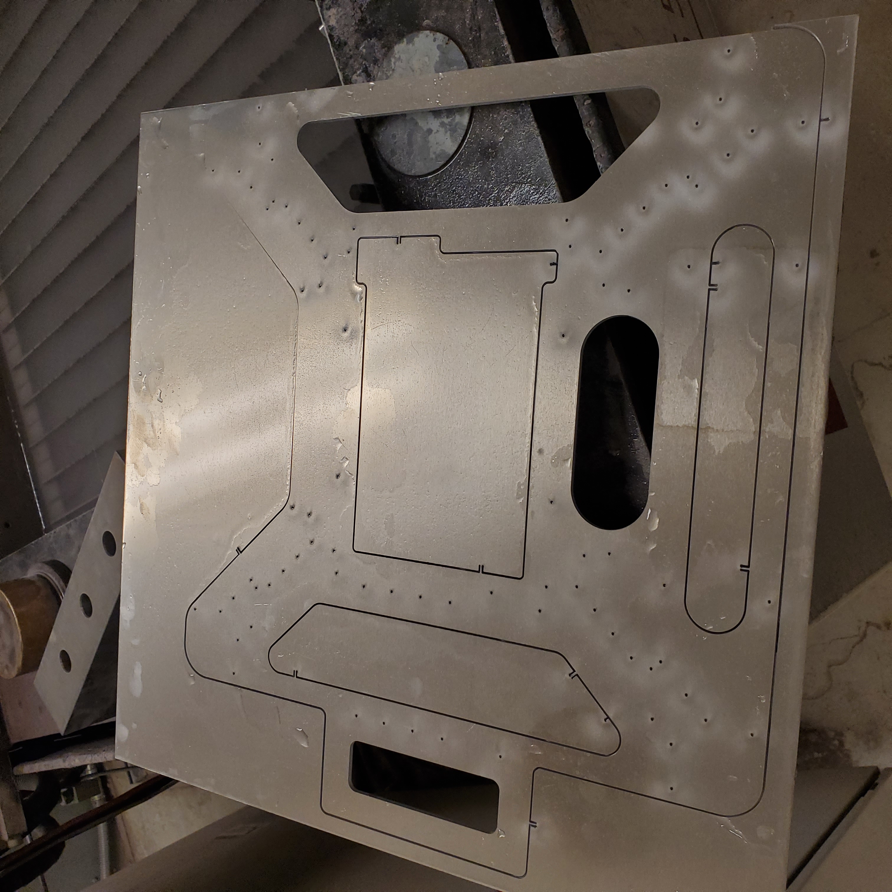
Mid-Waterjet Baseplate
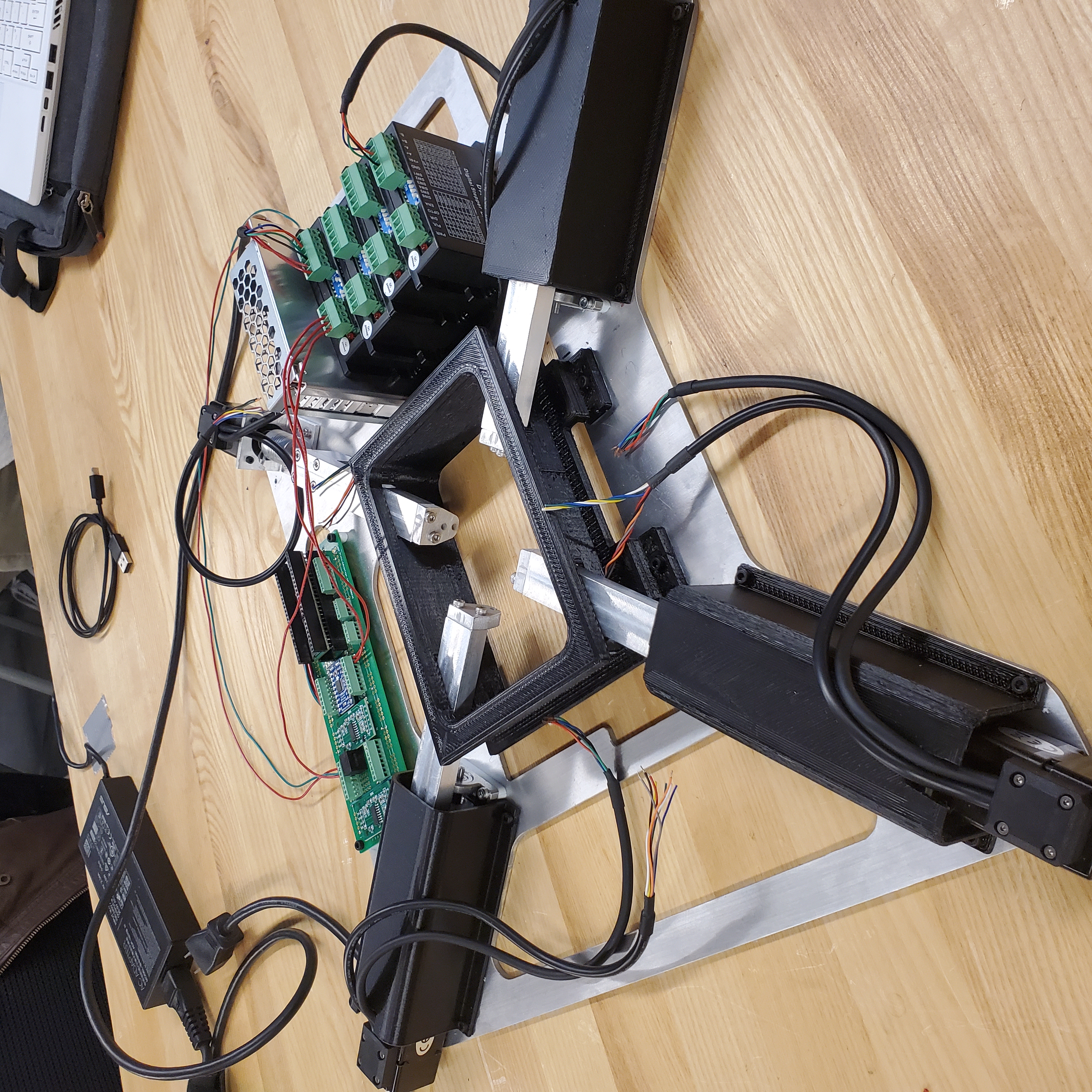
Rough Prototype Assembly
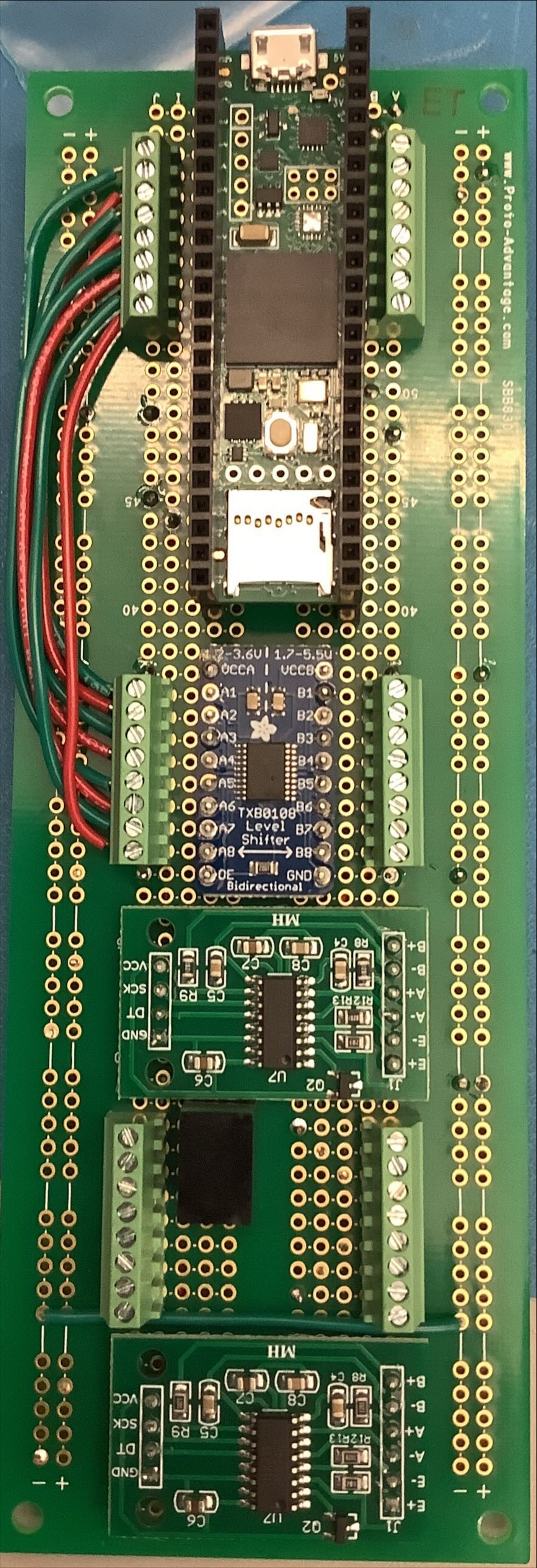
Protoboard Circuit
Electrical Design
The electrical design consisted of a Teensy 4.1 MCU, two ADC modules for our load cells, a logic level shifter for reading the encoders (as encoder signals were 5V, but Teensy pins are only rated for 3.3V)
For the external stepper motor drivers, a MOSFET switching circuit was used to allow current to flow through internal optocouplers (same issue of drivers using 5V and Teensy using 3.3V).
To clean up the wiring between the motors, encoders, drivers, and circuit board, 4-pin and 12-pin Mollex connectors were used.
We would have tried creating a PCB, however we were very short on time, so we used a prototyping board instead.
Software Design
For the software of this project, there were two main parts. The firmware for the i.MU RT1060, and the multithreaded Python control program.
The control program handles the user input, communication of commands to the MCU, and the recording/display of data in real-time.
The firmware of the device is written in C++ and is using FreeRTOS, with 3 main tasks below:
A picture of the control program (implemented in tkinter) is shown below.
General Software Flow Chart
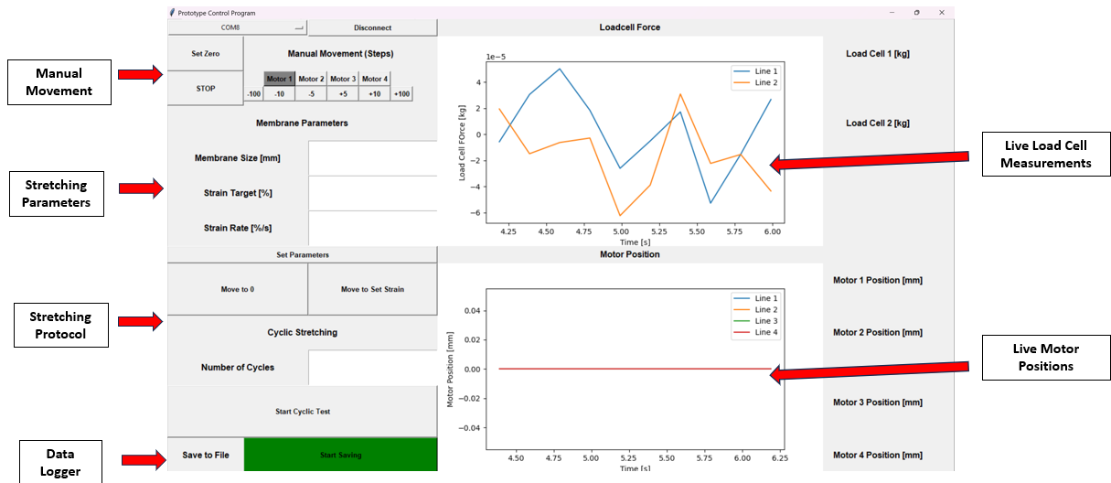
Control Program
Trajectory Generation Sketch
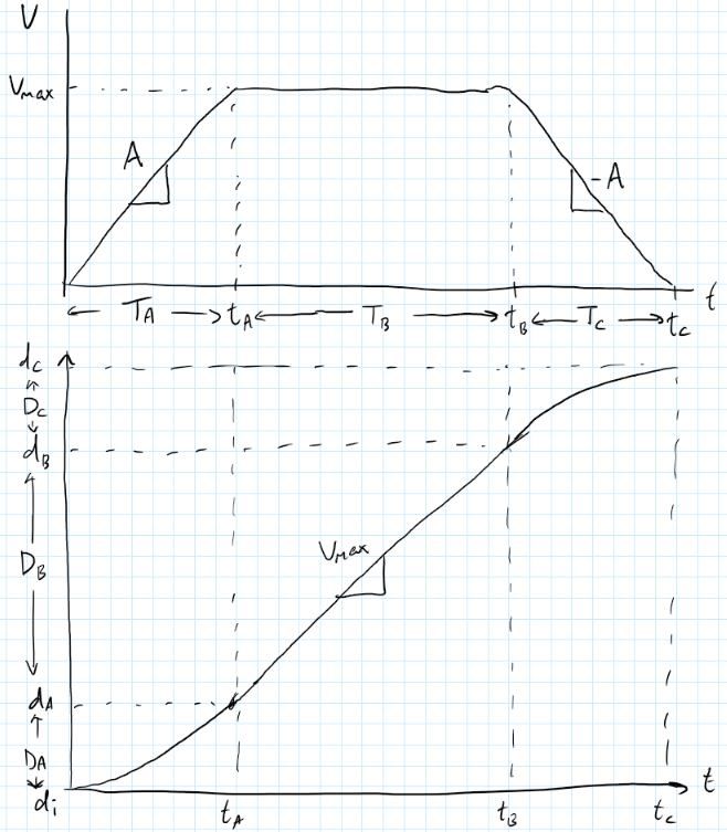
Trajectory Generation
For the motors to move from the current position to the target position, a trajectory was required, with a velocity ramp to prevent the stepper from skipping steps.
The inputs for generating a trajectory are the initial position, target position, and the average velocity, and from this, the required timer interrupts were set for stepping the motor and incrementing the stepping interrupt (acceleration).
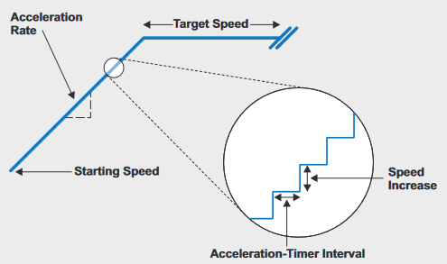
Stepper Acceleration Profile
Final Remarks
Through this project, I learned a lot about mechanical design, firmware, RTOS, python, OOP, electrical design, debugging, and integration.
This page is still under construction, as more information and reflections will be added.