A-Arm Design
September 2022 - January 2023
Project Overview |
Developed Skills |
||
|
|
|
|
Objective
This project was assigned to me by my team lead in the vehicle dynamics subteam of UBC Solar. I was tasked with designing the A-arms for our new vehicle Brightside.
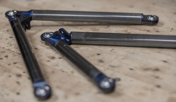
A-Arms used by Formula UBC
Initial Research
To start by defining the problem, other car team suspension designs were investigated.
We also consulted UBC Formula to see what they did for their A-arms - they used staked bearings into aluminum and carbon fiber tubes.
Concept Generation
The next step was to start concept generation for potential solutions for the A-arm.
It was important to keep in mind the potential pros and cons of each concept, which can be seen in the image on the right, and the two below.
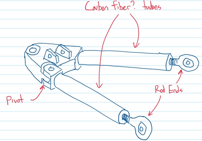
Concept sketch 1
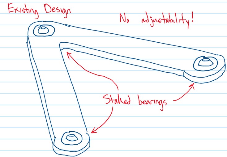
Concept sketch 2
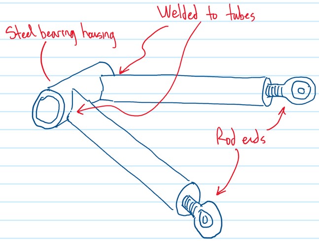
Concept sketch 3
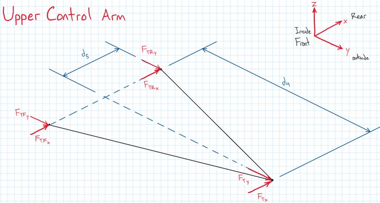
FBD for UCA
Force Calculation
The next step was to calculate the forces on the A-arms under the maximum loading condition (max brake, bump, and steer), so that we can determine how strong they need to be.
The initial UCA FBD following the method previously used on the team can be seen in the figure on the left.
Matrix Force Solving
The FBD method that was previously used on the team did not accurately represent the A-arms, so another approach was needed.
Looking at research papers on the calculation of forces in control arms, a method using matrices to represent any 6 member system was found.
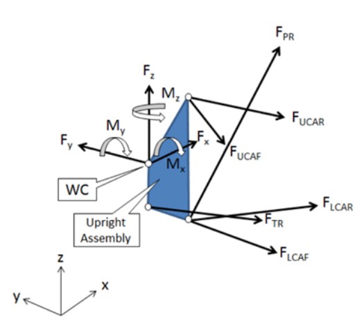
FBD for 6 member suspension
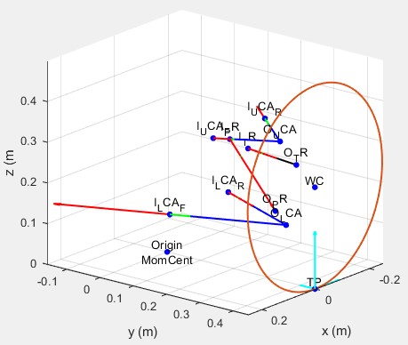
3D MATLAB suspension plot
MATLAB Script
To implement the calculations, MATALB was used to read any arbitrary input force and hardpoint locations from an excel spreadsheet for the A-arms to determine the forces experienced in the members.
The hard points and the forces are also plotted in 3D space. An output plot can be seen on the left.
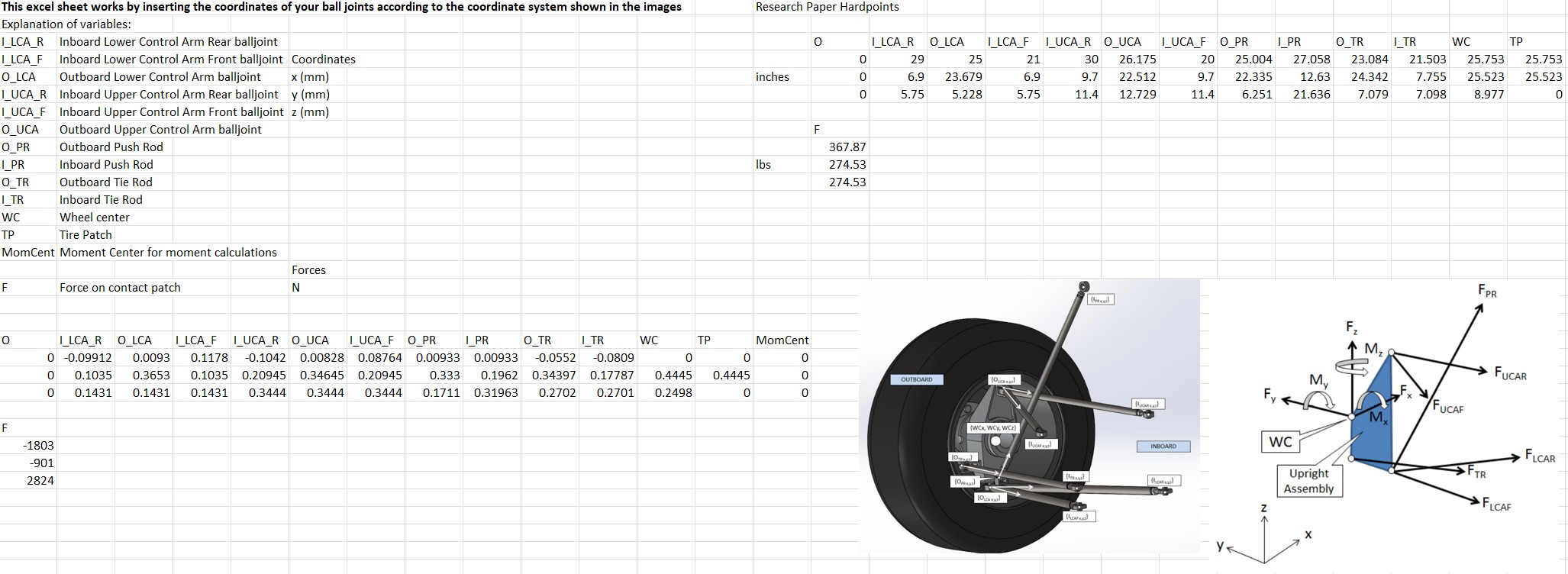
A-arm hardpoint and input force spreadsheet
A-Arm CAD
Using the forces calculated on the A-arms, the detailed design was done, choosing off-the-shelf components and creating CAD in Solidworks.
The factor of safety on the LCA front, which experiences the most force during the loading condition, was 4.5.
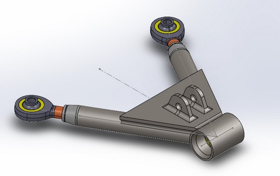
LCA CAD
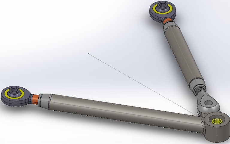
UCA CAD
Final Remarks
After the part was designed, I had to hand main leadership of the project off to another member on VDX, as I was going on a co-op term for Tesla in Texas.
This project was an incredible learning experience with doing thorough research into things our team ahd no history of, and implementing suspension design with a custom MATLAB script.